
Occlusion device and associated deployment method

a technology of occlusion device and associated deployment method, which is applied in the direction of dilators, occulders, surgery, etc., can solve the problems of undesirable formation, device not being particularly suited to address specific physiological conditions, and inability to occlusion the left atrial appendage by surgical techniques, etc., to achieve the effect of avoiding undesirable formation and avoiding undesirable formation

Active Publication Date: 2012-12-20
ST JUDE MEDICAL CARDILOGY DIV INC
View PDF8 Cites 86 Cited by
  • Summary
  • Abstract
  • Description
  • Claims
  • Application Information

AI Technical Summary

Benefits of technology

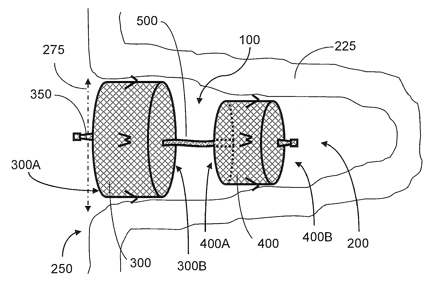
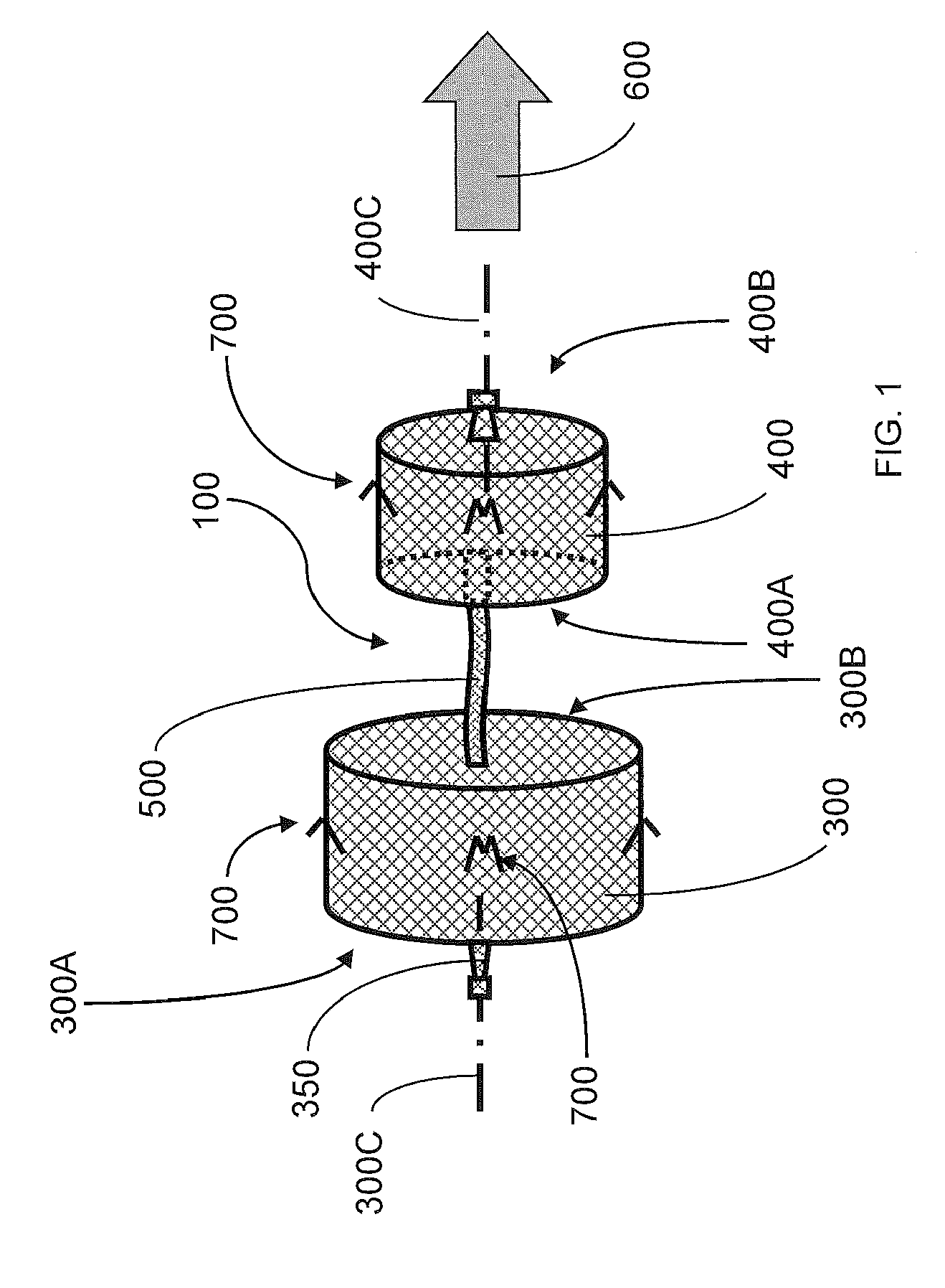
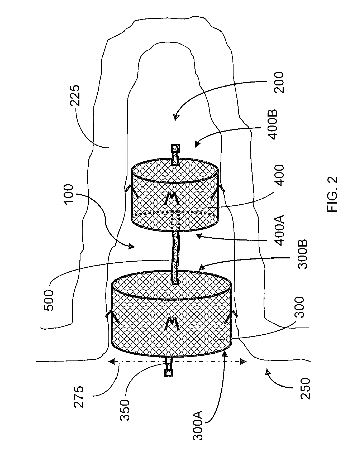
The present disclosure provides an occlusion device that can be used to occlude a cavity in a body. The device includes a first and second expandable portions that are inserted into the cavity through an opening. A connective element connects the two portions and the device can be collapsed for easy insertion. The device has retention members that are engaged with the body to secure the device in place. The method of using the device involves actuating the device to expand and engage the body. The technical effects of this disclosure include providing an effective and easy-to-use occlusion device for the treatment of various medical conditions.

Problems solved by technology

Such devices, however, may not be particularly suited to address specific physiological conditions such as, e.g., occlusion of the left atrial appendage (LAA), in order to reduce the risk of embolisms when the patient is undergoing atrial fibrillation.
During atrial fibrillation, the left atrial appendage may be a significant source of the undesirable formation of thrombus-embolis.
Also, occlusion of the left atrial appendage by surgical techniques may not always be possible and / or advisable.
Further, some such devices applied to occlude the left atrial appendage may sometimes be at risk of being undesirably expelled from the left atrial appendage due to, e.g., forces generated by atrial fibrillation.

Method used


Image

  • Occlusion device and associated deployment method
  • Occlusion device and associated deployment method
  • Occlusion device and associated deployment method

Examples


Embodiment Construction

[0016]The present disclosure now will be described more fully hereinafter with reference to the accompanying drawings, in which some, but not all aspects of the disclosure are shown. Indeed, the disclosure may be embodied in many different forms and should not be construed as being limited to the aspects set forth herein; rather, these aspects are provided so that this disclosure will satisfy applicable legal requirements. Like numbers refer to like elements throughout.

[0017]Aspects of the present disclosure provide a medical device for use in treating a target site within the body, such as occluding various vascular abnormalities, which may include, for example, occluding a Left Atrial Appendage (LAA), an Arterial Venous Malformation (AVM), a Patent Ductus Arteriosus (PDA), or the like. It is understood that the use of the term “target site” is not meant to be limiting, as the device may be configured to treat any target site, such as an abnormality, a vessel, an organ, an opening,...


PUM


Abstract

An occlusion device for occluding a cavity defined by a body is provided, and includes first and second laterally-expandable portions each formed of a woven tubular fabric and having opposed proximal and distal ends. The first portion is insertable into the cavity so as to be substantially disposed therein upon lateral expansion thereof. A connective element tethers the distal end of the first portion and the second portion, and is cooperable therewith to form a collapsible assembly extending along an insertion axis. Retention members, operably engaged with each of the first and second portions and spaced apart about a laterally outward surface thereof, are adapted to engage the body, after insertion of the collapsed assembly, second portion-first, into the cavity, and subsequent lateral expansion of the first and second portions, so as to retain the assembly substantially within the cavity. An associated deployment method is also provided.

Description

BACKGROUND OF THE DISCLOSURE[0001]1. Field of the Disclosure[0002]Aspects of the present disclosure are directed to implantable medical devices, more particularly to implantable medical devices configured to occlude vessels, cavities, appendages, or the like, within a body, and deployment methods associated therewith.[0003]2. Description of Related Art[0004]A variety of devices and / or techniques, along with materials for and methods of manufacturing such devices, have been developed to occlude a vessel or an opening in an organ (e.g., heart) of a patient.[0005]Such devices, however, may not be particularly suited to address specific physiological conditions such as, e.g., occlusion of the left atrial appendage (LAA), in order to reduce the risk of embolisms when the patient is undergoing atrial fibrillation. During atrial fibrillation, the left atrial appendage may be a significant source of the undesirable formation of thrombus-embolis. Also, occlusion of the left atrial appendage ...

Claims


Application Information

Patent Timeline
Patent Type & Authority Applications(United States)
IPC IPC(8): A61M29/00
CPCA61B17/12172A61B17/12122A61B17/12145
Inventor REN, BROOKE
Owner ST JUDE MEDICAL CARDILOGY DIV INC
Learn More