
Medical air mattress

a technology of air mattress and air mattress, which is applied in the field of medical air mattress, can solve the problems of inconvenient caretakers, inefficient use of time and human resources, and the design of detachable air cells b>90/b>

Active Publication Date: 2012-12-20
PICARD HEALTHCARE TECH DONGGUAN
View PDF7 Cites 11 Cited by
  • Summary
  • Abstract
  • Description
  • Claims
  • Application Information

AI Technical Summary

Benefits of technology

[0007]The main objective of the present invention is to provide independent air cells that can be deflated independently to receive the bedpan. The medical air mattress has a mattress body and an upper bedspread. The mattress body is formed by multiple air cells including independent air cells parallelly arranged as an air cell row. The upper bedspread covers the mattress body. The independent air cells are connected to the independent deflating unit to be deflated independently. When the patient needs to use the bedpan, the independent air cells are deflated to form a recess for receiving the bedpan so that the bedspread and the patient have no need to be moved.

Problems solved by technology

Patients lying on a mattress over a long period of time are susceptible to develop decubitus ulcers on multiple areas of the body due to continuous pressure.
The design of detachable air cells 90 is inconvenient to caretakers since the patient still needs to leave the conventional air mattress.
Furthermore, moving the patient and removing the upper bedspread requires two or more individuals.
This is an inefficient use of time and human resources, and the detachable air cells 90 do not function as what the original design expected.

Method used


Image

  • Medical air mattress
  • Medical air mattress
  • Medical air mattress

Examples


first embodiment

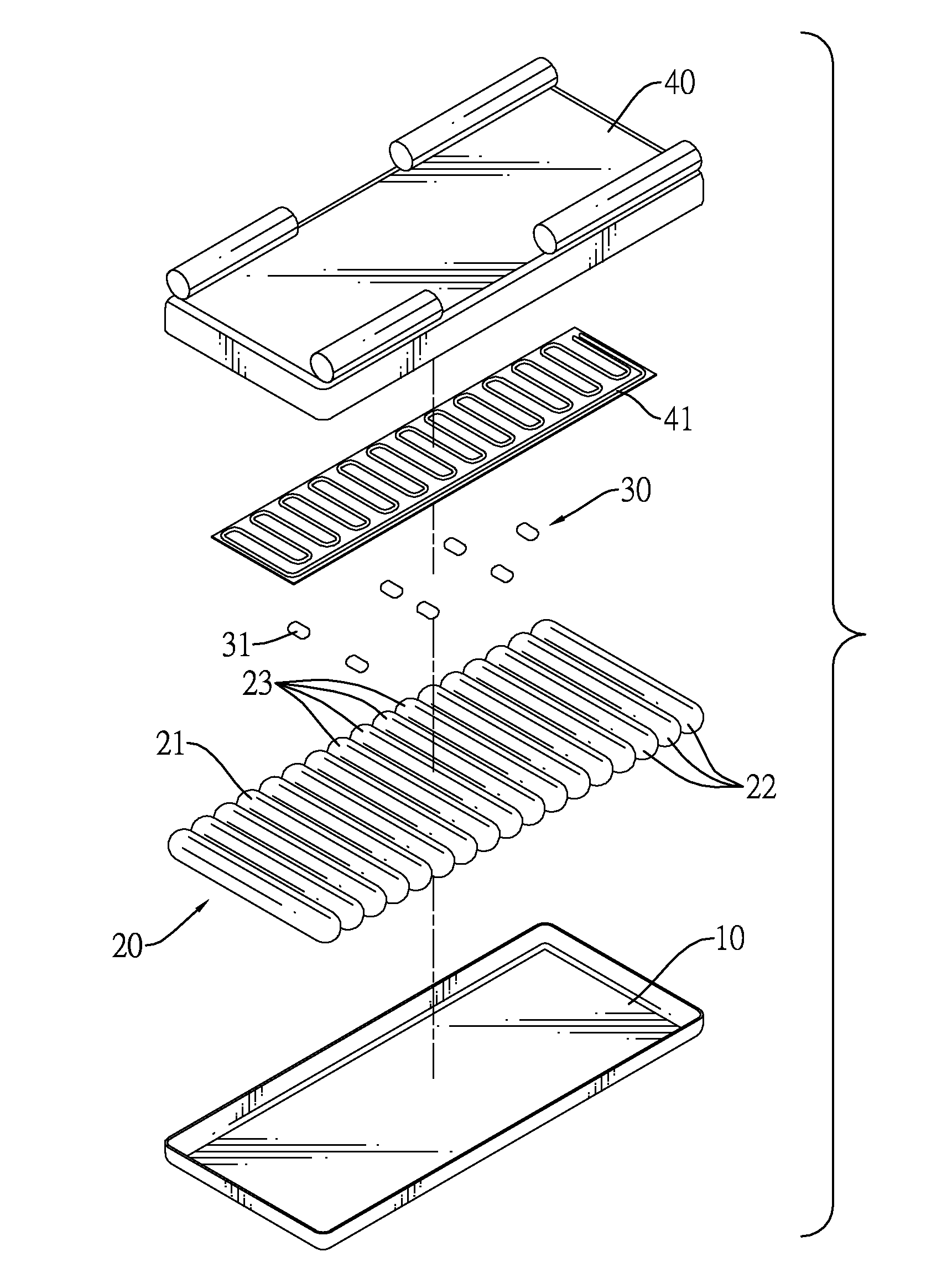
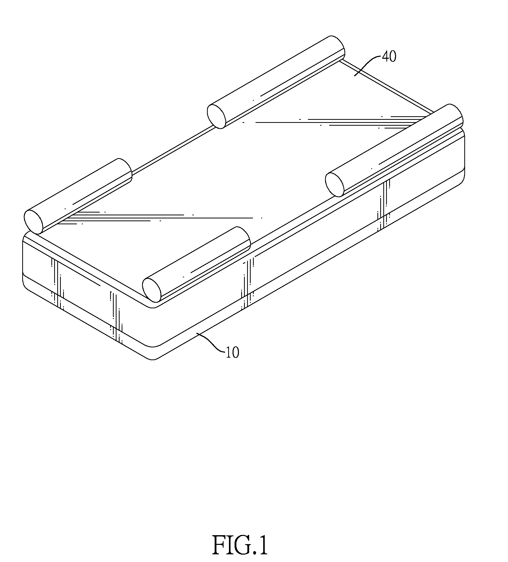
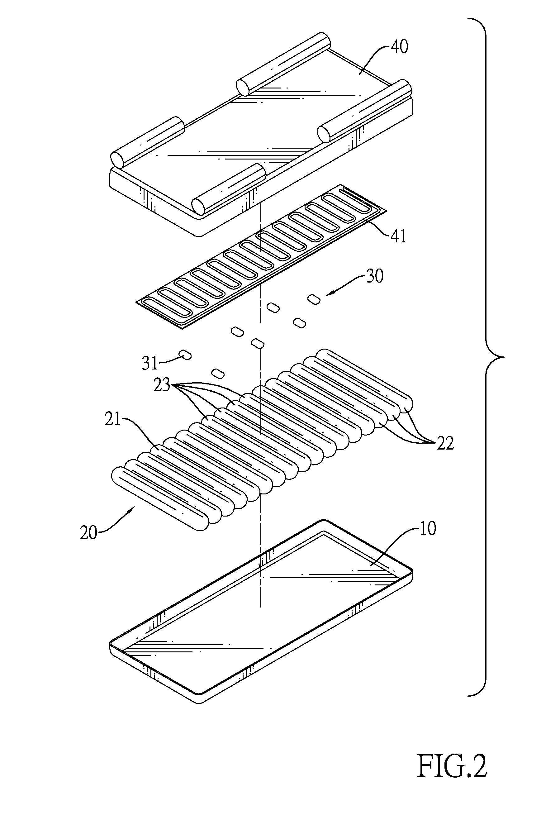
[0022]With reference to FIGS. 1 and 2, a medical air mattress in accordance with the present invention comprises a lower bedspread 10, a mattress body 20 and an upper bedspread 40.

[0023]The mattress body 20 is mounted on the lower bedspread 10 and comprises multiple body air cells 21, multiple head air cells 22 and multiple independent air cells 23. In a preferred embodiment, the mattress body 20 comprises three head air cells 22 and four independent air cells 23. Each body air cell 21, each head air cell 22, and the independent air cells 23 are tubular and respectively uniform in diameter. The body air cells 21, the head air cells 22 and the independent air cells 23 are parallel to each other and are arranged in a row to form an air cell row. The head air cells 22 are arranged at a head end in the air cell row, i.e. the head air cells 22 arranged at first to third in the air cell row. The independent air cells 23 are arranged at a central part in the air cell row, i.e. the independ...

second embodiment

[0037]When the medical air mattress as described is operated, the pump 51A, the alternating-valves and the solenoid valves are also actuated to inflate the air cells and to alternatively adjust the inflating. Since most operations are discussed above, only different operations are described below for the medical air mattress.

[0038]For mattress body 20A, when the pump 51A is operated, user may select different modes.

[0039]1. Full inflating mode:

[0040]The pump 51A is operated to inflate the body air cells 21A, the head air cells 22A and the independent air cells 23A.

[0041]2. Alternating inflating mode:

[0042]With reference to FIGS. 9 to 11, the pump 51A is operated and inflates the body air cells 21A and the independent air cells 23A at either odd or even rows of the air cell rows alternatively. When the body air cells 21A and the independent air cells 23A at odd rows of the air cell rows are inflated, the body air cells 21A and the independent air cells 23A at even rows of the air cel...


PUM


Abstract

A medical air mattress has a mattress body and an upper bedspread. The mattress body is formed by multiple air cells including independent air cells parallelly arranged as an air cell row. The upper bedspread covers the mattress body. The independent air cells are connected to the independent deflating unit to be deflated independently. When the patient needs to use the bedpan, the independent air cells are deflated to form a recess for receiving the bedpan so that the patient needs not to move.

Description

BACKGROUND OF THE INVENTION[0001]1. Field of the Invention[0002]The present invention relates to a medical air mattress, especially to a medical air mattress for anti-decubitus purposes.[0003]2. Description of the Prior Arts[0004]For patients who have physical difficulties with mobility or bedfast. Patients lying on a mattress over a long period of time are susceptible to develop decubitus ulcers on multiple areas of the body due to continuous pressure. In order to minimize or eliminate the development of decubitus ulcers caretakers must turn patient's body over or move the patient to alternate the areas of pressure on the body. The conventional medical air mattress was developed to assist in the manual movement of and alternating pressure areas on the patient using multiple odd and even cells alternatively inflated to generate wave motion for changing the contact areas of the patient's body. The conventional medical air mattress has the following inadequacies.[0005]With reference t...

Claims


Application Information

Patent Timeline
IPC IPC(8): A47C27/10A47C21/04
CPCA47C27/10A47C21/04
Inventor CHIANG, KUANG-NENGLIANG, HSIU-LUN
Owner PICARD HEALTHCARE TECH DONGGUAN
Learn More