Electronic device and ejection mechanism thereof

a technology of electronic devices and ejection mechanisms, which is applied in the direction of collapsible antennas, quick-releasable antenna elements, instruments, etc., can solve the problems of affecting the overall design of the appearance of portable electronic devices, affecting the signal receiving effect of antennas, and easily damage to antennas

Active Publication Date: 2012-12-13
WISTRON CORP
View PDF7 Cites 11 Cited by
  • Summary
  • Abstract
  • Description
  • Claims
  • Application Information

AI Technical Summary

Benefits of technology

[0006]Therefore, an object of the present invention is to provide an electronic device, including an ejection mechanism, which has a simple structure and is capable of retracting an electronic element (such as an antenna) into a casing, so as to result in convenience when the electronic device is carried, or ejecting the electronic element out of the casing, so as to clearly receive signals.
[0017]Another object of the present invention is to provide an ejection mechanism for an electronic device, which has a simple structure and is capable of retracting an electronic element into a casing, or ejecting the electronic element out of the casing.
[0020]The electronic device of the present invention is advantageous in that, through the design of the ejection mechanism, the electronic element can be received and concealed within the casing, or can be ejected out of the casing.

Problems solved by technology

Some antennas are fixedly mounted inside the housing of the portable electronic device, which easily causes the signals received by the antennas to be shielded by the housing, thereby affecting adversely the signal receiving effect of the antennas.
Although such an antenna mounting method does not affect the signal receiving effect of the antennas, it impairs the overall design of the appearance of the portable electronic device, and causes easily damage to the antennas due to collision or friction occurring when the portable electronic device is being carried.

Method used


Image

  • Electronic device and ejection mechanism thereof
  • Electronic device and ejection mechanism thereof
  • Electronic device and ejection mechanism thereof

Examples


Embodiment Construction

[0040]The above-mentioned and other technical contents, features, and effects of this invention will be clearly presented from the following detailed description of the two preferred embodiments in coordination with the reference drawings.

[0041]Before this invention is described in detail, it should be noted that, in the following description, similar elements are designated by the same reference numerals.

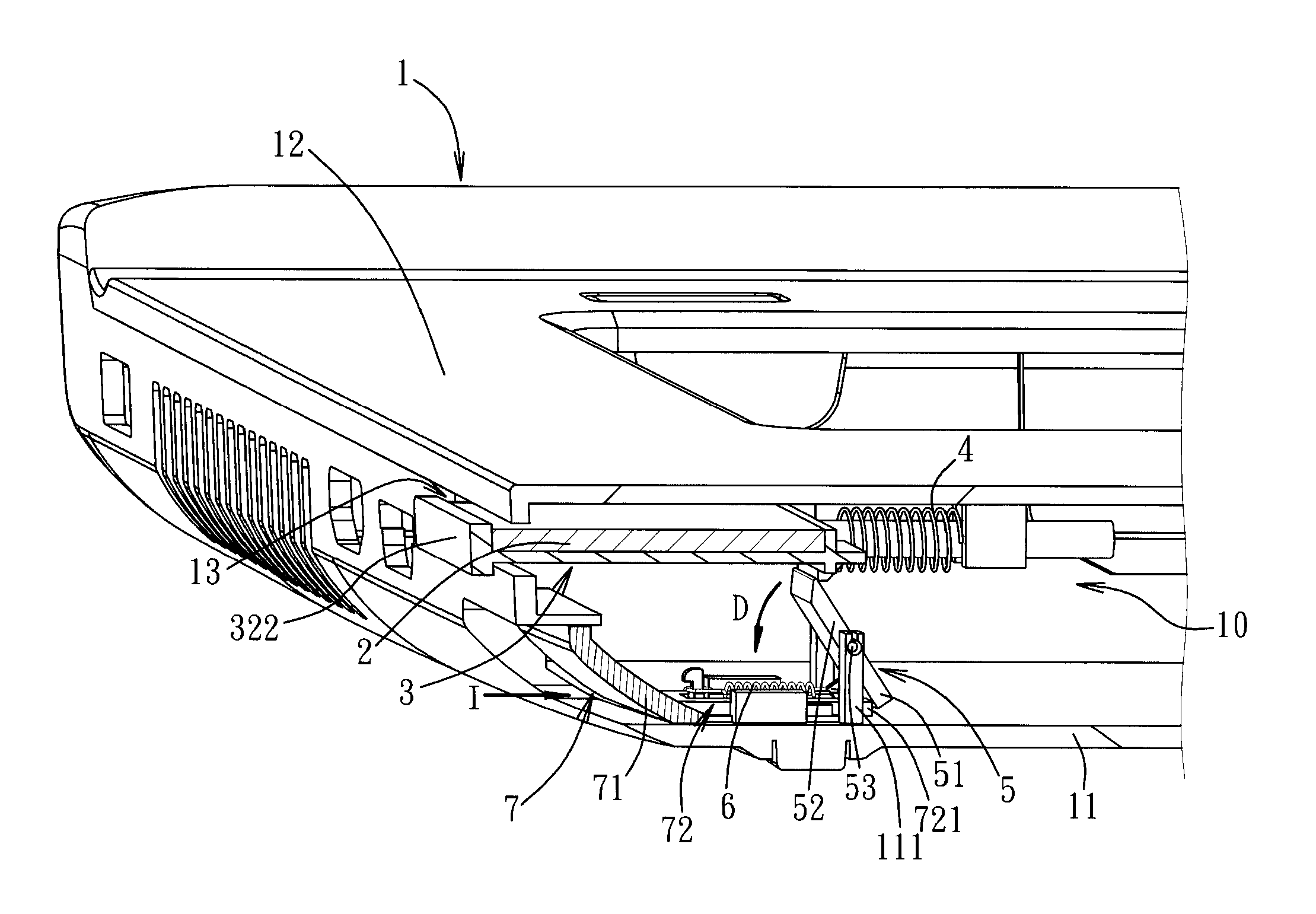
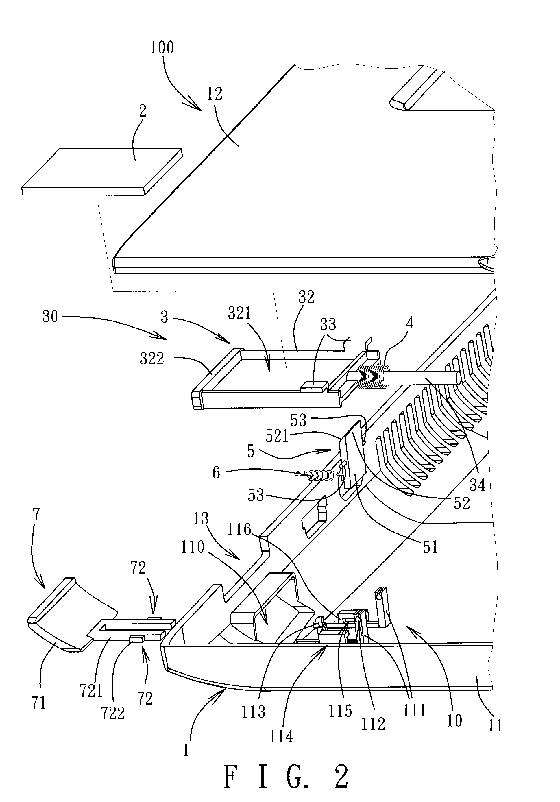
[0042]As shown in FIGS. 1 and 2, a first embodiment of an electronic device 100 of the present invention is exemplified using a notebook computer. Alternatively, the electronic device 100 may be a tablet computer, a mobile phone, a personal digital assistant or the like. In this embodiment, the electronic device 100 comprises a casing 1, an electronic element 2, and an ejection mechanism 30. The casing 1 is exemplified using a host casing, which may be installed therein with, for example, a mother board, a hard disk, and an optical disk drive (not shown). A rear end of the casing 1...


PUM


Abstract

An electronic device comprises a casing, an electronic element, and an ejection mechanism. The casing has a receiving space and an opening. The ejection mechanism includes: a holder for holding and carrying the electronic element to pass through the opening to be exposed outside the casing; a first biasing spring biasing the holder to project outwardly from the opening; a stopping member rotatably pivoted to the casing and contactable with a projection of the holder; a second biasing spring biasing the stopping member to contact the projection, and having an elastic modulus greater than that of the first biasing spring; and a releasing member operable for driving the stopping member to detach from the projection.

Description

CROSS-REFERENCE TO RELATED APPLICATION[0001]This application claims priority of Taiwanese Patent Application No. 100119967, filed on Jun. 8, 2011, the disclosure of which is incorporated herein by reference.BACKGROUND OF THE INVENTION[0002]1. Field of the Invention[0003]The invention relates to an electronic device, and more particularly to an electronic device having an ejection mechanism for ejecting an electronic element.[0004]2. Description of the Related Art[0005]A conventional portable electronic device (such as a notebook computer or tablet computer) typically has a wireless network access function, and antennas are disposed on the portable electronic device to receive wireless signals. Some antennas are fixedly mounted inside the housing of the portable electronic device, which easily causes the signals received by the antennas to be shielded by the housing, thereby affecting adversely the signal receiving effect of the antennas. In addition, some antennas are fixedly mounte...

Claims


Application Information

Patent Timeline
IPC IPC(8): H05K7/10
CPCG06K13/0818G06K13/0831H01Q1/088H01Q1/2266G06F1/1698
Inventor LIAO, CHIEN-JUNG
Owner WISTRON CORP
Why Eureka
Try Eureka