
Work vehicle and work vehicle control method

a technology for work vehicles and control methods, applied in the direction of machines/engines, road transportation, instruments, etc., can solve the problems of increased fuel consumption (amount of consumed fuel), vehicle cannot move forward and come to a stop, engine output continues to be high, etc., to achieve the effect of reducing traction force, increasing lift force, and improving fuel consumption

Active Publication Date: 2012-12-06
KOMATSU LTD
View PDF3 Cites 28 Cited by
  • Summary
  • Abstract
  • Description
  • Claims
  • Application Information

AI Technical Summary

Benefits of technology

[0006]However, the above-described prior art is control by which the engine speed is reduced after the vehicle has entered a stalled state. Accordingly, the prior art does not inhibit the vehicle from entering a stalled state in advance. Therefore, in the case of an inexperienced operator, the vehicle is readily made to stall and the engine speed is reduced on each occasion. Accordingly, ease of operation is liable to be reduced. An objective of the present invention is to provide a work vehicle and a work vehicle control method that can improve fuel consumption and suppress a reduction in ease of operation.

Problems solved by technology

For example, when an inexperienced operator excessively depresses the accelerator and presses the work implement into the soil during excavation, the vehicle cannot move forward and comes to a stop.
In this stalled state in which the vehicle has stopped moving, the engine output continues to be high and fuel consumption (amount of consumed fuel) is therefore increased.
When the amount of operation of the accelerator operation member is low, the traction force is unlikely to become excessively high in relation to the lift force.
Therefore, the vehicle is unlikely to enter a stalled state even when the traction force is increased as the height position of the work implement is increased.

Method used


Image

  • Work vehicle and work vehicle control method
  • Work vehicle and work vehicle control method
  • Work vehicle and work vehicle control method

Examples


Embodiment Construction

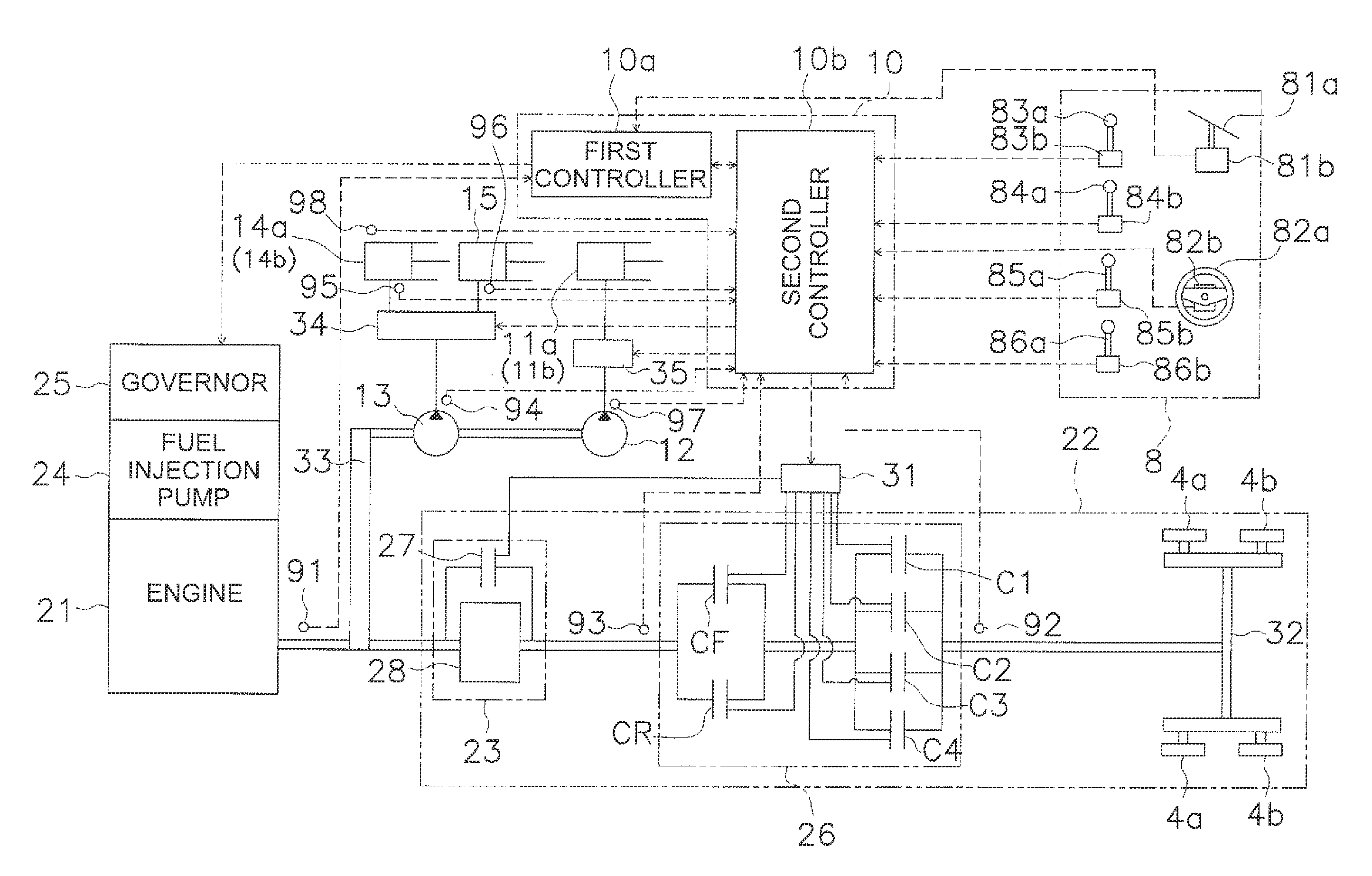
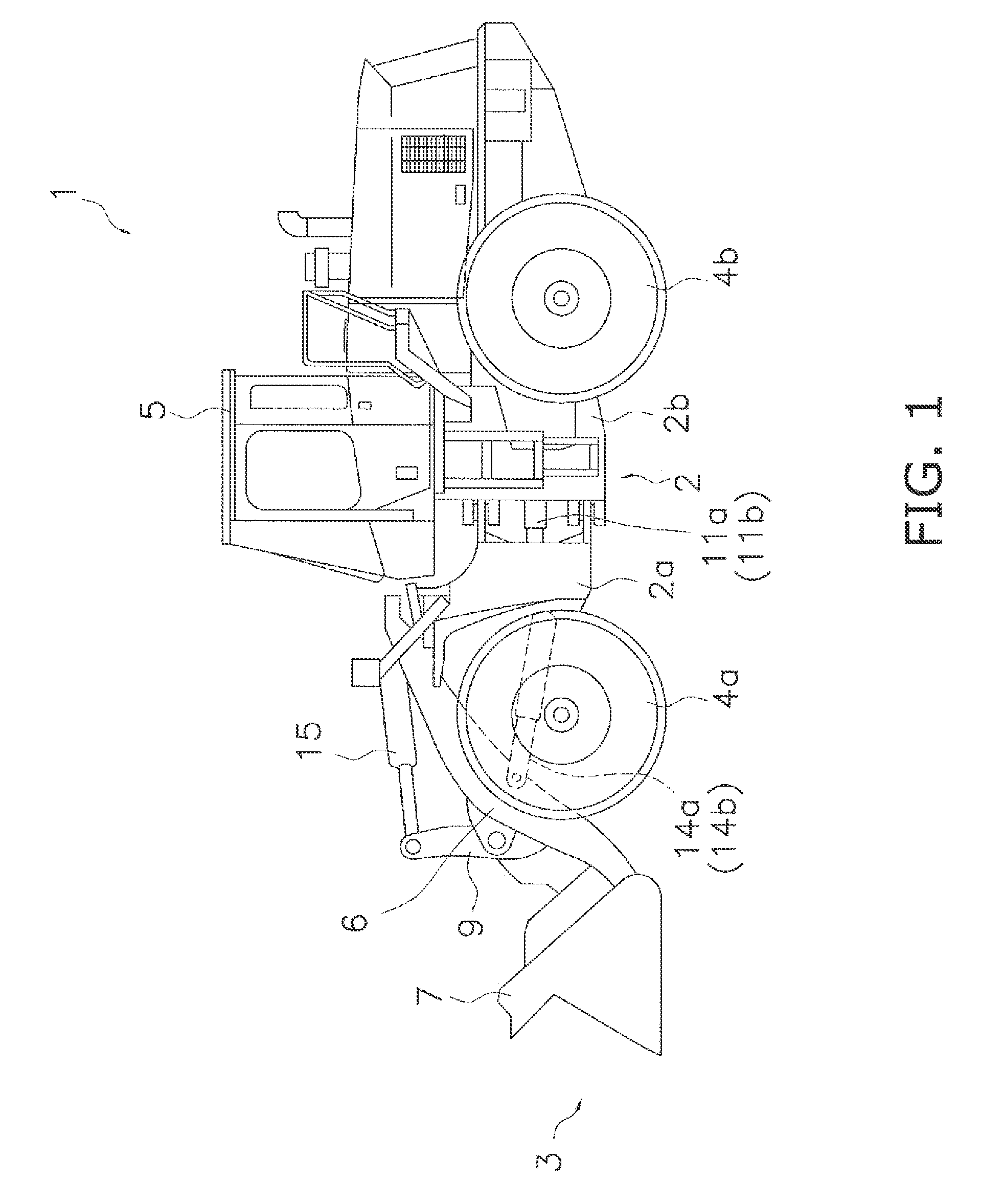
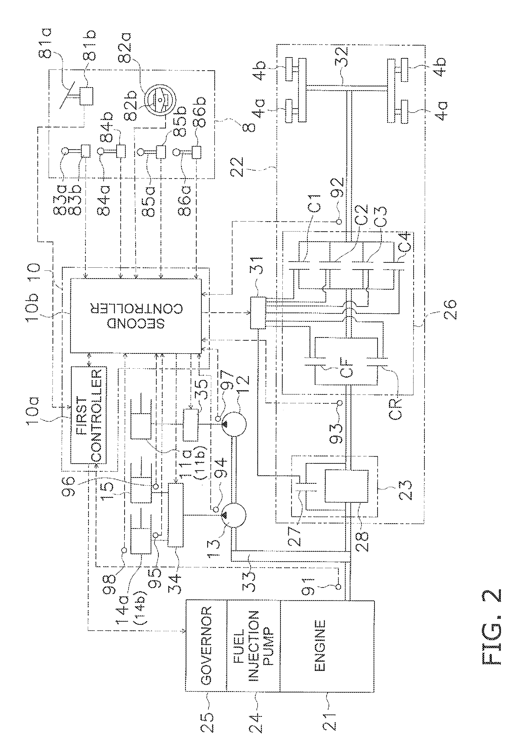
[0050]The work vehicle 1 according to an embodiment of the present invention is shown in FIGS. 1 and 2. FIG. 1 is a view of the external appearance of the work vehicle 1, and FIG. 2 is a schematic view showing the configuration of the work vehicle 1. The work vehicle 1 is a wheel loader, and the work vehicle 1 is capable of traveling by front wheels 4a and rear wheels 4b being rotatably driven, and is capable performing desired work using a work implement 3.

[0051]The work vehicle 1 comprises a vehicle body frame 2, a work implement 3, wheels 4a and 4b, and a driver cabin 5, as shown in FIG. 1.

[0052]The vehicle body frame 2 has a front vehicle body section 2a and a rear vehicle body section 2b. The front vehicle body section 2a and the rear vehicle body section 2b are connected to each other so as to allow pivoting in the left and right directions. A pair of steering cylinders 11a and 11b are provided from the front vehicle body section 2a to the rear vehicle body section 2b. The ste...


PUM


Abstract

A work vehicle includes a drive source, a travel device, a hydraulic pump, a work implement, a traction force detector, a lift force detector and a controller. The traction force detector is configured to detect traction force of the work vehicle. The lift force detector is configured to detect lift force for raising the work implement. The controller is configured to compare a predetermined threshold and a ratio between the lift force and the traction force, and to execute traction force reduction control for reducing the traction force when an increase in the lift force is required.

Description

CROSS-REFERENCE TO RELATED APPLICATIONS[0001]This application claims priority to Japanese Patent Application No. 2010-048986 filed on Mar. 5, 2010, the disclosure of which is hereby incorporated herein by reference in its entirety.TECHNICAL FIELD[0002]The present invention relates to a work vehicle and a work vehicle control method.BACKGROUND ART[0003]In a wheel loader or other automatic work vehicle, traction force (travel drive force) and work implement drive force are obtained from an engine as a shared drive source. For example, traction force is obtained from a so-called HST hydraulic travel device or via a torque converter. The work implement drive force is obtained via hydraulic pump driven by the engine.[0004]In such a work vehicle, there are many cases in general practice in which travel, loading, and other work are carried out simultaneously, and it is important to distribute the output of the engine with good balance to travel and to the work implement. For example, in ex...

Claims


Application Information

Patent Timeline
IPC IPC(8): E02F9/20
CPCB60W10/30B60W30/1886E02F9/2246E02F9/2253Y02T10/76E02F9/2292F02D29/04F16H61/472E02F9/2289E02F3/431E02F9/2029E02F9/2079E02F9/2296E02F9/265B60D1/248B60D1/62Y02T10/60
Inventor ASAMI, SATOSHIKOIZUMI, JUNISHII, SHOTARO
Owner KOMATSU LTD
Learn More