
Wind Turbine

a wind turbine and fluid power technology, applied in the direction of motors, electrical equipment, engine fuctions, etc., can solve the problems of high torque, drag on the turbine, and low performance of the vertical axis wind turbine, so as to maximize the energy generated by the wind, reduce the torque, and the effect of convenient availability

Inactive Publication Date: 2012-12-06
WESBY PHILIP +1
View PDF4 Cites 14 Cited by
  • Summary
  • Abstract
  • Description
  • Claims
  • Application Information

AI Technical Summary

Benefits of technology

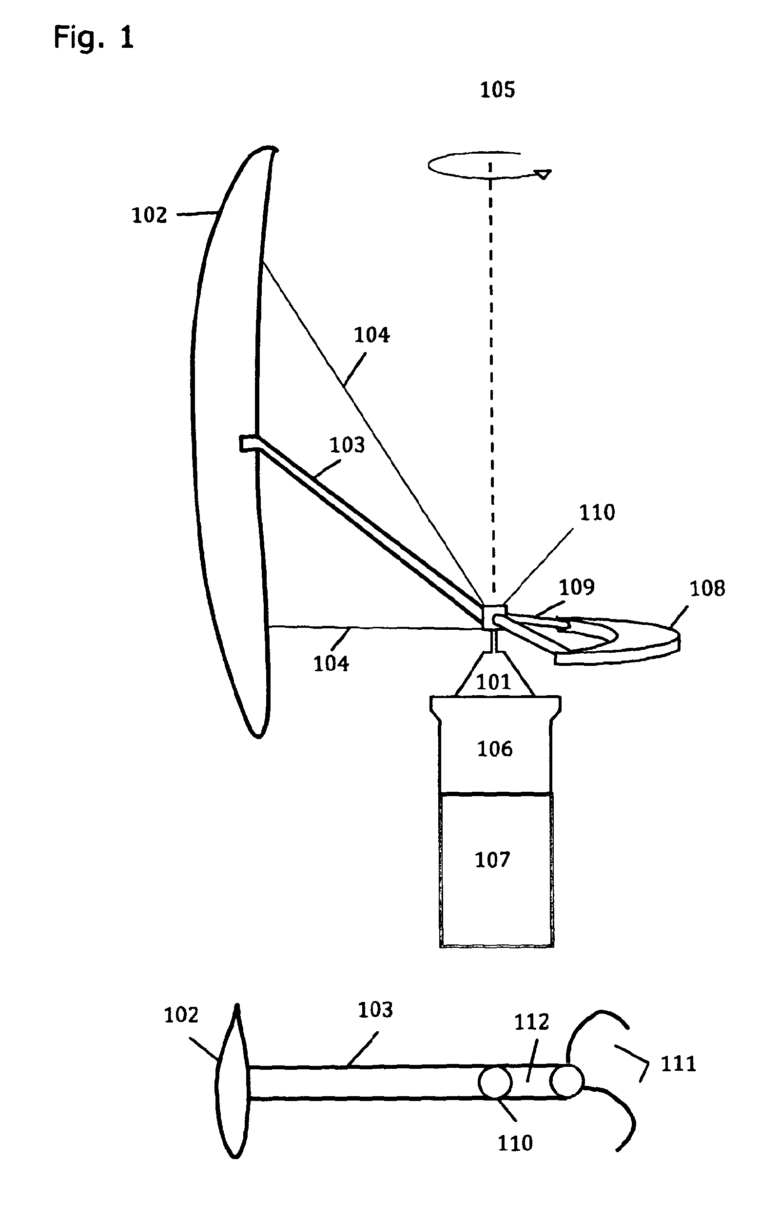
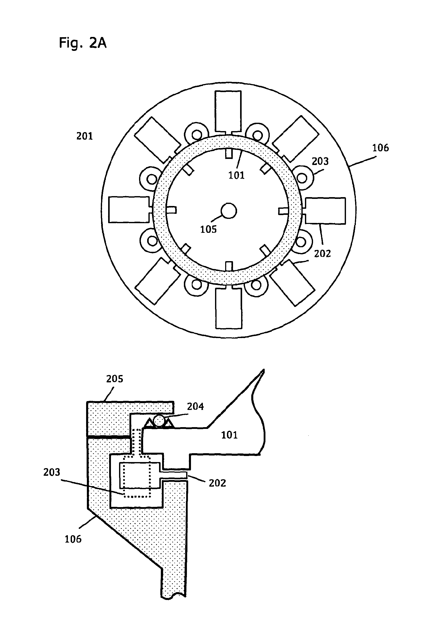
[0016]It is a further object of one embodiment of the present invention to provide a system and method for fluid power conversion for wind turbines wherein the blades of the turbine are integrated with a central support hub which rotates with the movement of the blades and which comprises a large diameter and which is securely coupled to a power generation support means by a plurality of roller bearings or direct drive gears or the like which are located in the structure of the said support means such that the movement of the central support hub causes the said roller bearings or the like to move wherein each is coupled with a power generation component.
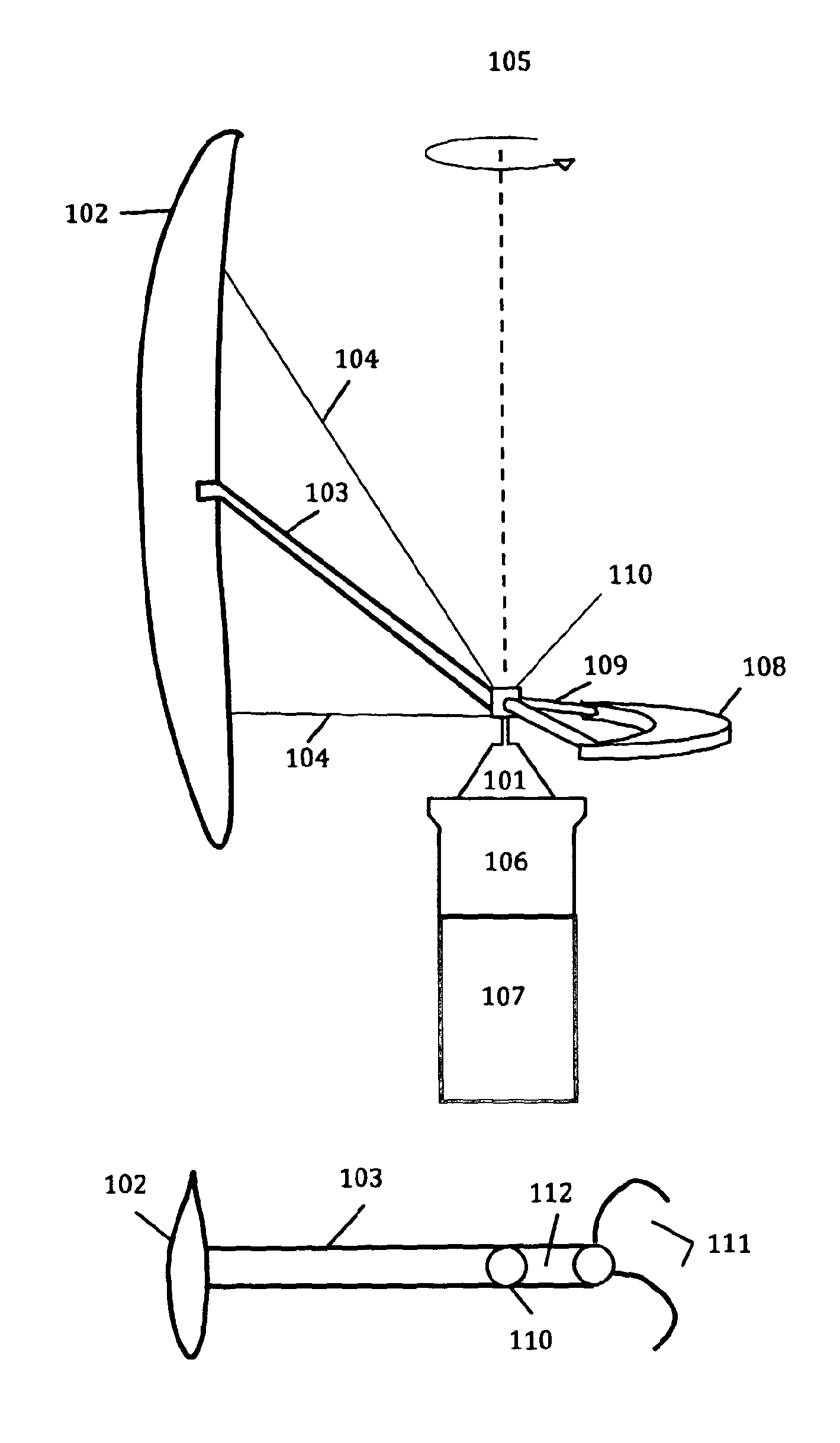
[0032]In a preferred embodiment, a single vertical blade comprising a high performance profile is connected to the central support hub by way of a strut held at an inclined angle to the plane of rotation. A number of support wires between the central hub and the blade further may be added to increase the control of the blade structure and a counter-weight serves to balance the turning VAWT blade and support strut.

Problems solved by technology

Generally, vertical axis wind turbines (VAWTs) often suffer from lower performance when compared to horizontal axis wind turbines (HAWTs) due to their blades not comprising optimised chord lengths and cross sectional profiles.
In addition, while VAWTs are always facing the wind whatever the direction of the wind, and can generate power as the wind direction changes, the turning blades move into and out of the wind as they turn, which causes a stress load on the turbine blades and support struts and wires, once per revolution.
The strut support of the VAWT is also moving into and out of the wind once per revolution and this provides drag on the turbine and thereby reduces its efficiency in power generation.
The gearbox is often a point of failure in wind turbines due to the high loading and changing forces exerted on the transmission system during operation.
Shock loading of the transmission system occurs at the instant that power is taken from the wind and the shock loads can lead to failure of the gearbox.
Today, it is standard practice to use multiple-blade vertical axis wind turbines but the high number of blades reduces the efficiency of the turbines and thus renders them uneconomical to deploy.
Large turbines having power outputs above 100 kW are very heavy to construct and each requires a very robust support tower to support the weight of the gearbox and an expensive electric generator, which is coupled to a single high torque drive shaft.
No systems are presently known to the applicants, which address this market need in a highly effective and economic way.
Further to the limitations of existing technologies used for fluid power conversion in wind turbines, and so far as is known, no optimised system and method for fluid power conversion is presently available which is directed towards the specific needs of this problem area as outlined.

Method used


Image

  • Wind Turbine
  • Wind Turbine
  • Wind Turbine

Examples


Embodiment Construction

[0039]Reference will now be made in detail to some specific embodiments of the invention including the best modes contemplated by the inventor for carrying out the invention. Examples of these specific embodiments are illustrated in the accompanying drawings. While the invention is described in conjunction with these specific embodiments, it will be understood that it is not intended to limit the invention to the described embodiments. On the contrary, it is intended to cover alternatives, modifications, and equivalents as defined by the appended claims.

[0040]The following description makes full reference to the detailed features which may form parts of different embodiments as outlined in the objects of the invention. In the following example reference is made to a system comprising electric generators and gearpumps while it is to be understood that the invention covers other embodiments which use other types of hydraulic pumps such as piston pumps and vane pumps and the like. Othe...


PUM


Abstract

A system and method for fluid power conversion is described which can provide the basis for a new and improved wind turbine suitable to manufacture a horizontal axis (HAWT) or vertical axis (VAWT) turbine at one of a range of different power classes such as from 4 kiloWatts to 10 MegaWatts. In the case of the VAWT, the wind turbine comprises one or more turbine blades moving around a vertical axis wherein each blade is anchored to a central hub by at least one strut and by at least two cable wires. In the case of the HAWT, the wind turbine comprises two or more turbine blades moving around a horizontal axis wherein each blade is anchored to a central hub. The turbine central hub comprises a relatively large diameter, which is coupled to a power generation support structure via a plurality of roller bearings or the like. As the central hub turns, it drives the roller bearings, which are each coupled with a separate power generation component such as an electric generator or a hydraulic gearpump. This configuration of a large diameter central hub coupled to multiple electrical power generators and or gearpumps wherein each power generation component of the system is controlled by an intelligent central system controller, provides versatile control of the net output power generated by the turbine and thereby maximizes the efficiency of the turbine over a range of wind speeds. The electric generators and or hydraulic gearpumps may together comprise a range of power conversion ratings to further optimise and control the power output of the wind turbine over a range of wind speeds.

Description

BACKGROUND OF THE INVENTION[0001]The invention relates to a system and method for fluid power conversion, which is suitable for turbine power generation systems. More particularly, it relates to a system and method for fluid power conversion in wind turbines, which is highly suited to both Vertical Axis Wind Turbines (VAWTs) and Horizontal Axis Wind Turbines (HAWTs) which may form the base technology for the manufacture of wind turbines at one of a range of different power classes such as at 4 kiloWatts, 40 kW, 400 kW, 4 MW and 10 MW. In the case of the VAWT, the wind turbine comprises one or more turbine blades moving around a vertical axis wherein each blade is anchored to a central hub by at least one strut and by at least two cable wires. In the case of the HAWT, the wind turbine comprises two or more turbine blades moving around a horizontal axis wherein each blade is anchored to a central hub. The turbine central hub comprises a relatively large diameter, which is coupled to a...

Claims


Application Information

Patent Timeline
Patent Type & Authority Applications(United States)
IPC IPC(8): F03D9/00
CPCF03D3/005F05B2240/301F03D7/022F03D7/026F03D7/042F03D7/06F05B2220/706F05B2240/21F05B2240/2212F05B2250/312F05B2260/40F05B2260/4021F05B2260/406Y02E10/74F03D3/061Y02P70/50
Inventor WESBY, PHILIPTURNER, CHRISTOPHER
Owner WESBY PHILIP
Learn More