Vessel with submersible hulls

a technology of submerged vessels and hulls, which is applied in the direction of floating buildings, bulkheads/piles, vessel construction, etc., can solve the problems of difficult extrapolation to higher, weak limit in size of mono-hull vessels, and inability to perform o&m operations on production platforms

Inactive Publication Date: 2012-12-06
GRUPO DE ING OCEANICA
View PDF2 Cites 6 Cited by
  • Summary
  • Abstract
  • Description
  • Claims
  • Application Information

AI Technical Summary

Benefits of technology

[0032]Various types of propulsion can be adapted to this vessel, but the complex reverse tractor type is preferred which avoids having to use the rudder.
[0055]The solution of reduction of viscous resistance by the breaking of the outer layer by an air-flow brings about a revolution in ship building as it makes it possible to achieve speeds with levels of consumption unthinkable up until now.

Problems solved by technology

Given the size of the vessel and the speed required mono-hull vessels are strongly limited by the optimisation of resistance to advance, especially that due to the formation of waves.
1.—Raise the hull out of the water by dynamic support, by the use of submersible wings. This solution is not advisable from a certain size, as the support of the wings increases with size as a function of the square of the overall length (area of the wings) while weight grows with size as a function of the cube of the overall length (volume of displacement) and hence it is difficult to extrapolate to higher sizes a design of hydro-wing vessel which has worked well in smaller sizes.
2.—Submerge the displacement in such a way that floating is as smooth as possible, as this is the main (although not the only) cause of resistance due to wave formation.
But the greater problem of this type, for the objectives pursued, is that its upper works cannot be lifted above the height of the waves, and hence although it is true that due to its geometry it has little resistance from wave formation, it cannot avoid the resistance of waves formed in the sea and the difficulties and risks of navigation with sea made up of large waves, and hence in these circumstances it could not perform O&M operations for production platforms.

Method used


Image

  • Vessel with submersible hulls
  • Vessel with submersible hulls
  • Vessel with submersible hulls

Examples


Embodiment Construction

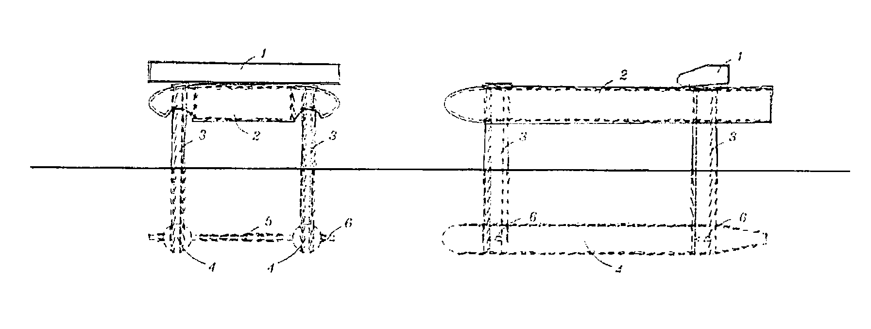
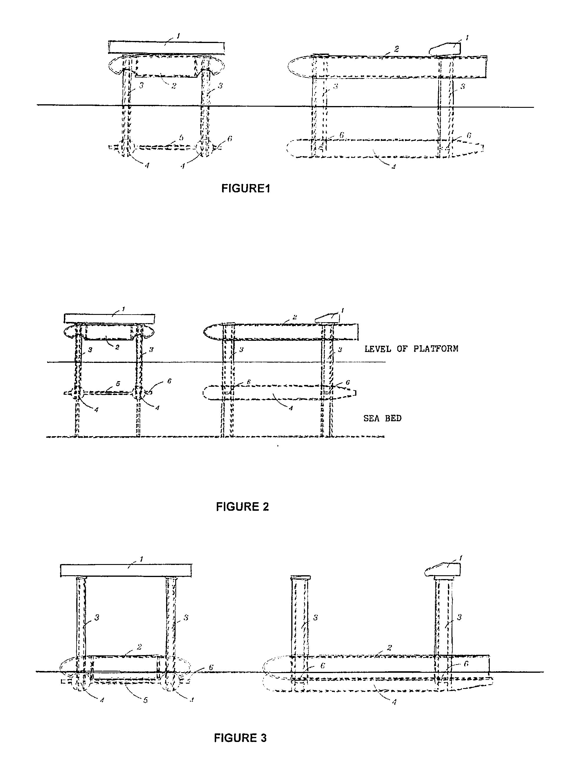
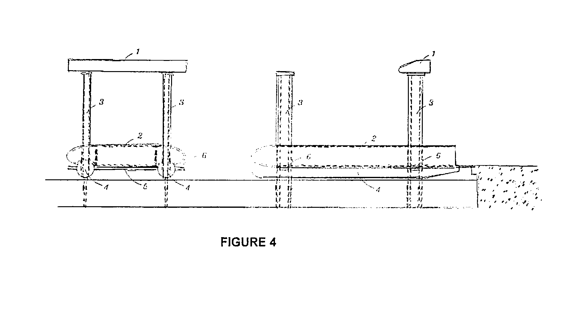
[0027]The new design of vessel forming the subject-matter of this invention is characterised by having its displacement made up of two parallel submerged bodies, clearly cylindrical in cross-section or as hydrodynamic as possible, joined by hydrodynamic profiles.

[0028]Four hydrodynamic legs are located in the confluence between the cylinders and the profiles capable of supporting a platform or loading zone which can move (up or down) on the legs to raise itself above the level of the waves.

[0029]Within the legs there are hydraulic pistons of equal length and which cross the cylinders and are joined to tangential plates outside the cylinders for deep support of the pistons.

[0030]The upper works (or non-submerged part of the vessel) has pinions which can move it above the legs which are fitted with a rack to the level necessary to navigate at sea level. The rack and pinion system can be replaced by any equivalent system of vertical displacement.

[0031]The engine room, motors, the bridg...


PUM


Abstract

New design of vessel with submersible hulls which can transport large cargos at high speed sailing above the waves and which is made up of two parallel submerged bodies (4), clearly cylindrical in cross-section or as hydrodynamic as possible, joined by hydrodynamic profiles (5).Four hydrodynamic legs (3) are located in the confluence between the cylinders (4) and the profiles (5) capable of supporting a platform or loading zone (2) which can move (up or down) on the legs (3) which have a system of vertical displacement so as to raise itself above the level of the waves.The parallel bodies of submerged displacement (4) joined to the hydro-dynamic profiles (5) can be completely covered with a textile of permeable sheets of porosity less than the size of a molecule of water and greater than that of a molecule of air and air can be pumped into the interior. The air molecules escape via the pores breaking the outer layer and separating the water molecules from the submerged area so as to reduce viscous friction to a significant degree.The lower works can be raised to the level of the sea to load and material in their interior or to enter shallow water ports.

Description

SECTOR OF THE INVENTION[0001]This invention comes within the technical sector of navigation and design of vessels for the carrying out of any type of maritime operation of loading, transport of goods and persons, in commercial usages of large- and small-scale ports, fishing, sport, and in any sea conditions. More specifically it falls within the sector of design of vessels specially conceived for supplying, the installation, operation and maintenance of sea production platforms.BACKGROUND TO THE INVENTION[0002]There is currently a growing need to use the natural resources of the sea to supply the needs of the population. It is for that reason that a great number of marine platforms or structures are being developed, either floating or fixed, for the production and / or extraction of resources.[0003]For the supply of materials and equipment for their manufacture, the installation, operation, maintenance and supplying of the same during production it is necessary to have the appropriate...

Claims


Application Information

Patent Timeline
Patent Type & Authority Applications(United States)
IPC IPC(8): B63B1/12E02D5/74B63B1/38B63B1/10
CPCB63B1/107Y02T70/125B63B1/40Y02T70/10B63B1/10B63B1/38
Inventor DEL CAMPO Y RUIZ DE ALMODOVAR, CESAR
Owner GRUPO DE ING OCEANICA
Why Eureka
Try Eureka