
Magnetic Conveyor Systems, Apparatus and Methods Including Moveable Magnet

a magnetic conveyor and moving magnet technology, applied in the field of magnetic conveyor systems, apparatus and methods including moveable magnets, can solve problems such as fluid spillage, and achieve the effect of improving the magnetic conveyor system

Inactive Publication Date: 2012-11-22
SIEMENS HEALTHCARE DIAGNOSTICS INC
View PDF3 Cites 80 Cited by
  • Summary
  • Abstract
  • Description
  • Claims
  • Application Information

AI Technical Summary

Benefits of technology

[0006]Still other aspects, features, and advantages of the present invention may be readily apparent from the following detailed description by illustrating a number of exemplary embodiments and implementations, including the best mode contemplated for carrying out the present invention. The present invention may also be capable of other and different embodiments, and its several details may be modified in various respects, all without departing from the spirit and scope of the present invention. Accordingly, the drawings and descriptions are to be regarded as illustrative in nature, and not as restrictive. The drawings are not necessarily drawn to scale. The invention is to cover all modifications, equivalents, and alternatives falling within the spirit and scope of the invention.

Problems solved by technology

The act of magnetically coupling to the racks may, in operation, contribute to spillage of the fluid samples in the sample containers.

Method used


Image

  • Magnetic Conveyor Systems, Apparatus and Methods Including Moveable Magnet
  • Magnetic Conveyor Systems, Apparatus and Methods Including Moveable Magnet
  • Magnetic Conveyor Systems, Apparatus and Methods Including Moveable Magnet

Examples


Embodiment Construction

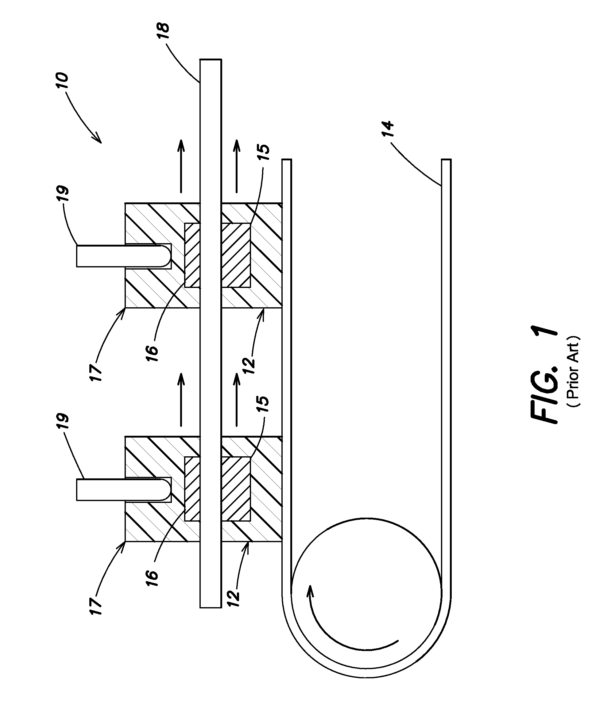
[0021]In prior art magnetic conveyor systems 10, as best shown in FIG. 1, magnetic couplings 12 mounted to a conveyor belt 14 include fixed magnets 15 which magnetically couple with ferromagnetic members 16 of sample racks 17 to move the sample racks along a conveyor surface 18. The sample racks 17 carry one or more sample containers 19 and include the ferromagnetic member 16, such as a steel plate, on a bottom thereof. Increasing a strength of the conveying magnets improves reliability of transport. The inventors herein recognized that as the field strength of the conveying magnets is increased, such prior art systems may accelerate the rack unacceptably fast when the magnet 15 of the magnetic coupling 12 approaches the sample rack 17. This may result the rack 17 jumping towards the magnetic coupling 12 and spillage of the sample fluid contained in the open sample container 19. This spillage condition may be unacceptable because it may result in loss of the patient sample, contamin...


PUM


Abstract

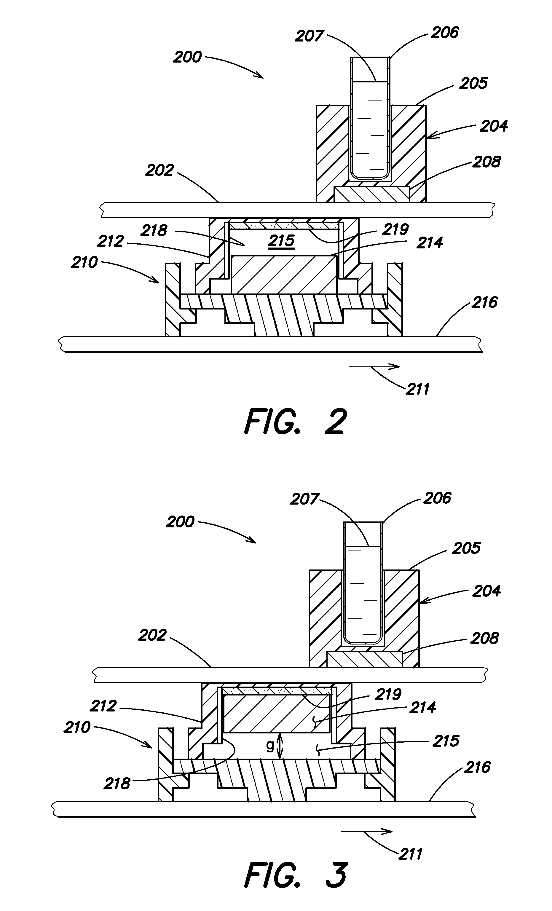
Disclosed are magnetic conveyor systems and apparatus having a magnetic coupling with a housing and moveable magnet therein. The moveable magnet is substantially constrained in one dimension and adapted to move in another. The moveable magnet is adapted to magnetically couple with an attracting portion of a sample rack and move the rack along a conveying surface. Ease of transfer of sample racks is provided while minimizing spillage from the open sample containers therein. Method of operating the conveyor system are provided, as are other aspects.

Description

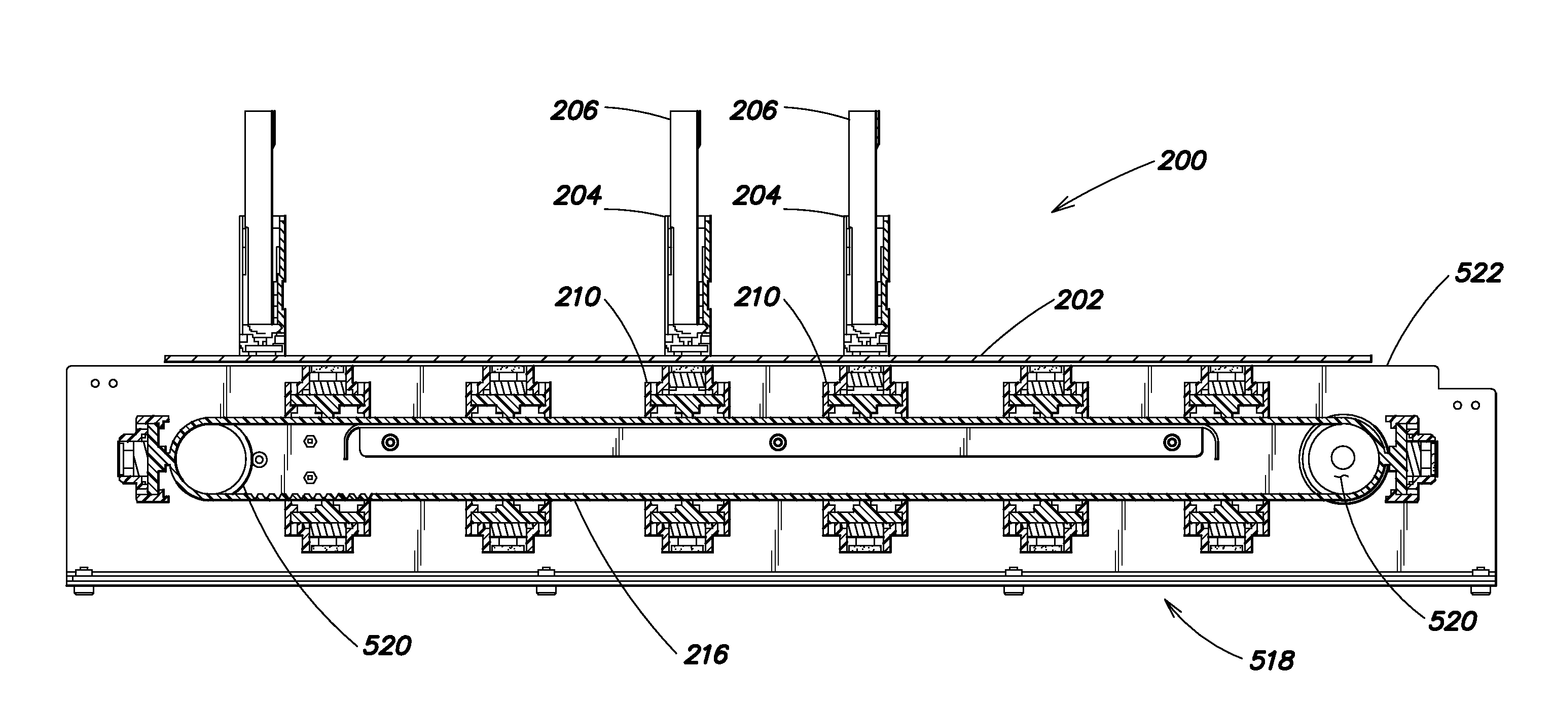
FIELD OF THE INVENTION[0001]The present invention relates generally to apparatus, systems and methods for conveying sample racks to and from clinical analyzers.BACKGROUND OF THE INVENTION[0002]In the testing of bodily fluid samples (otherwise referred to as “specimens”) in automated testing systems (e.g., clinical analyzers), sample containers (such as test tubes, sample cups, vials, and the like) may be conveyed in sample racks along a conveyor system to the test system. One type of conveyor system couples magnetically to sample racks to move the racks along a conveying surface. The act of magnetically coupling to the racks may, in operation, contribute to spillage of the fluid samples in the sample containers. Accordingly, apparatus, systems and methods are desired that may allow for less disruption of the sample containers and sample racks as they are being conveyed to and from the clinical analyzer thereby reducing the propensity for spillage from the sample containers.SUMMARY O...

Claims


Application Information

Patent Timeline
IPC IPC(8): G01N35/04
CPCB65G15/58Y10T436/113332G01N35/026B65G54/025
Inventor ARIFF, GREGORYEVERS, TIMOTHYSAWANT, MILINDVIJAY, TUMKUR
Owner SIEMENS HEALTHCARE DIAGNOSTICS INC
Learn More