Analyzing method of phase information, analyzing program of the phase information, storage medium, and x-ray imaging apparatus

a phase information and analysis program technology, applied in imaging devices, instruments, nuclear engineering, etc., can solve the problem of inaccurate phase wave front image and achieve the effect of improving image noise resistan

Inactive Publication Date: 2012-11-22
CANON KK
View PDF1 Cites 30 Cited by
  • Summary
  • Abstract
  • Description
  • Claims
  • Application Information

AI Technical Summary

Benefits of technology

[0017]The above windowed Fourier transform method disclosed in Non Patent Literature 1 has an advantage of improving the resistance of image to noise in comparison with a conventionally used general Fourier transform method, but has the following disadvantage.
[0023]The present invention provides an analyzing method of phase information and the like capable of further improving a resolution thereof in an analysis using a windowed Fourier transform method.

Problems solved by technology

In particular, when the full width at half maximum of the window function is small, a constant pattern is superimposed on a phase wave front recovery image and thus an accurate phase wave front image may not be derived.

Method used


Image

  • Analyzing method of phase information, analyzing program of the phase information, storage medium, and x-ray imaging apparatus
  • Analyzing method of phase information, analyzing program of the phase information, storage medium, and x-ray imaging apparatus
  • Analyzing method of phase information, analyzing program of the phase information, storage medium, and x-ray imaging apparatus

Examples


embodiments

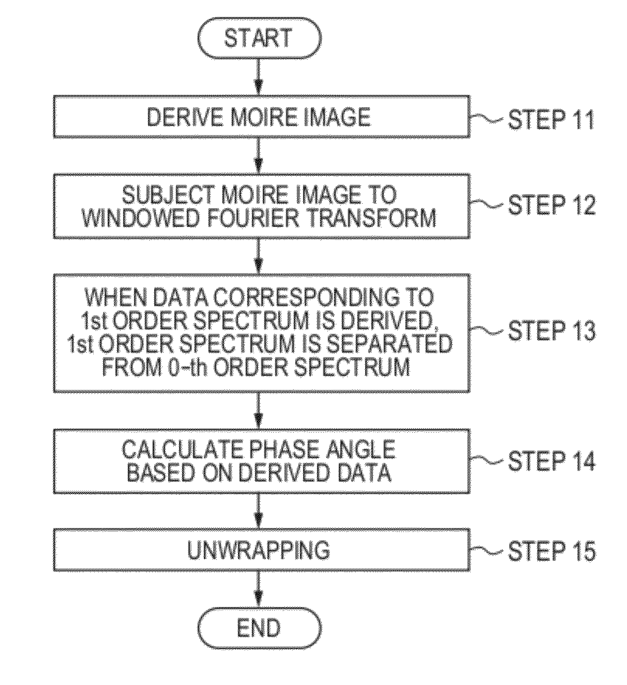
[0092]Hereinafter, the present embodiment will be described.

first embodiment

[0093]In the present embodiment, an example of calculation by computer simulation will be described. The parameters used in the simulation are as follows.

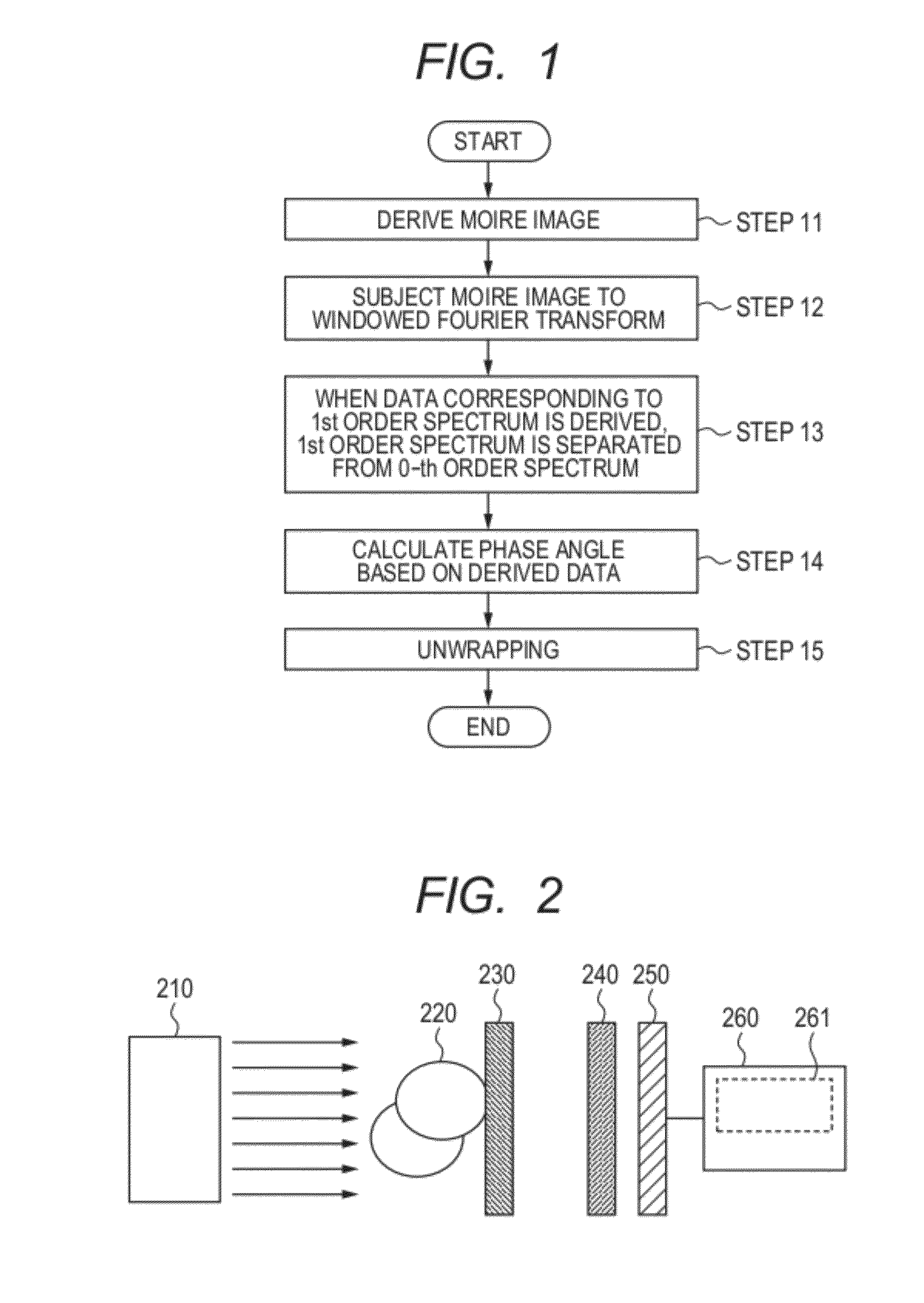
[0094]First, an assumption is made that the X-rays emitted from the X-ray source 210 are coherent incident X-rays each with an energy of 17.7 keV and a wavelength of 0.7 Å, namely, with a constant phase wave front.

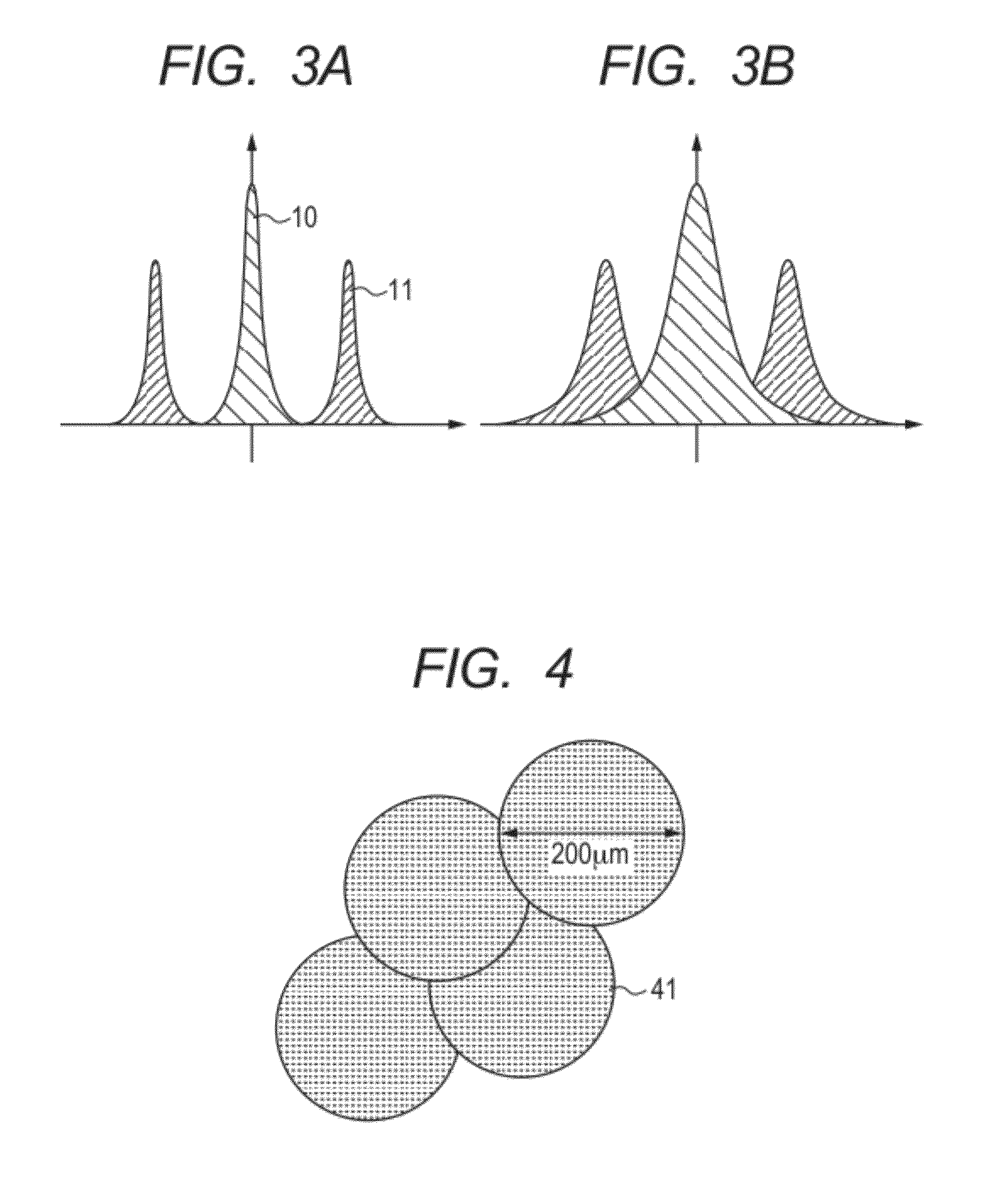
[0095]The incident X-rays undergo a change in phase wave front by the object 220. The object used in the present embodiment is assumed to be made of four calcium phosphate spheres 41 each with a diameter of 200 μm overlapped as illustrated in FIG. 4.

[0096]Here, a 4 μm stripe π grating (stripe pattern) is used as the above described phase grating.

[0097]Here, the 4 μm stripe π grating refers to a stripe pattern in which as illustrated in FIG. 5A, a portion 501 with the phase of the incident X-ray subjected to π change and a portion 502 with the phase subjected to no change are provided at 1:1 ratio, and a pair of stripe pat...

second embodiment

[0108]Unlike the first embodiment using a stripe pattern as the phase grating, the second embodiment uses a 4 μm checkerboad π grating (checkerboad pattern).

[0109]Here, the 4 μm checkerboad π grating refers to a shape in which a portion 511 with the phase subjected to π change and a portion 512 with the phase subjected to no change alternately appear into a checkerboad pattern as illustrated in FIG. 5B.

[0110]The size of the full width at half maximum of the window function is two pixels on an image in the same manner as in the first embodiment. The moiré image detected at this time by the detector 250 has a 2D structure as illustrated in FIG. 8.

[0111]FIGS. 9A to 10B each illustrate a differential image of the recovered phase wave front for comparison between the prior art and the present embodiment. FIG. 9A illustrates a phase wave front differential image along the Y-axis in prior art. FIG. 9B illustrates a phase wave front differential image along the Y-axis in the second embodime...


PUM

PropertyMeasurementUnit
energyaaaaaaaaaa
diameteraaaaaaaaaa
widthaaaaaaaaaa

Abstract

An analyzing method for deriving phase information by analyzing a periodic pattern of moiré comprises steps of: subjecting at least a part of the periodic pattern of moiré to a windowed Fourier transform by a window function; calculating analytically, based on the moiré subjected to the windowed Fourier transform, information of a first spectrum carrying the phase information, and information of a second spectrum superimposed on the information of the first spectrum; and separating the information of the first spectrum from the information of the second spectrum, to derive the phase information.

Description

TECHNICAL FIELD [0001]The present invention relates to an analyzing method of phase information, an analyzing program of the phase information, a storage medium, and an X-ray imaging apparatus.[0002]In particular, the present invention relates to a technique for calculating differentiation of a phase wave front of an original incident wave or the phase wave front from a periodic pattern such as a moiré (an interference pattern or an intensity pattern) created by interfering with an incident wave such as light with any phase wave front.BACKGROUND ART [0003]There has been known a technique for causing interference using waves with various wavelengths including light and X-rays for use in shape measurement of an object to be detected.[0004]According to the above measurement technique, (coherent) incident light with a constant phase wave front is irradiated on the object and reflected or transmitted.[0005]It has been known that the reflected light or transmitted light changes in wave fr...

Claims


Application Information

Patent Timeline
Patent Type & Authority Applications(United States)
IPC IPC(8): G01N23/04G06F17/14
CPCG01B11/254G21K2207/005G01B15/00
Inventor NAGAI, KENTARO
Owner CANON KK
Why Eureka
Try Eureka