
Method and apparatus for monitoring biological activity and controlling aeration in an activated sludge plant

Inactive Publication Date: 2012-11-22
PROCESS KINETICS
View PDF4 Cites 8 Cited by
  • Summary
  • Abstract
  • Description
  • Claims
  • Application Information

AI Technical Summary

Benefits of technology

[0007]In the range 0-3.0 mg / l, increasing DO increases the rate of nitrification. However, DO has an affect on the efficiency with which oxygen is transferred from the blower air into the mixed liquor. The lower the DO the more oxygen will be transferred from the same airflow.
[0008]The present invention is directed to a method and apparatus for monitoring biological activity in an activated sludge plant controlled by conventional techniques to provide the operator with useful information on the biological activity in individual aeration zones. The present invention is further directed to a method and apparatus for controlling the aeration of the activated sludge plant in a manner that provides a stable process that is capable of reducing energy used in aeration. This is accomplished by changing the nitrification rate to fully utilize the time available for treatment. The technique endeavors to utilize minimum DO values in each aeration zone while achieving desired nitrification. This results in an efficient exchange of oxygen into the mixed liquor which minimizes air volume, thereby realizing energy savings.

Problems solved by technology

For zones where the rate of ammonia removal cycles over a 24 hour period between being only marginally affected by ammonia concentration to being strongly affected, traditional DO set-point control using PID logic cannot operate in a stable fashion.
Hence, while the accuracy and response of DO sensors has improved dramatically, stable DO control has remained elusive.

Method used


Image

  • Method and apparatus for monitoring biological activity and controlling aeration in an activated sludge plant
  • Method and apparatus for monitoring biological activity and controlling aeration in an activated sludge plant
  • Method and apparatus for monitoring biological activity and controlling aeration in an activated sludge plant

Examples


Embodiment Construction

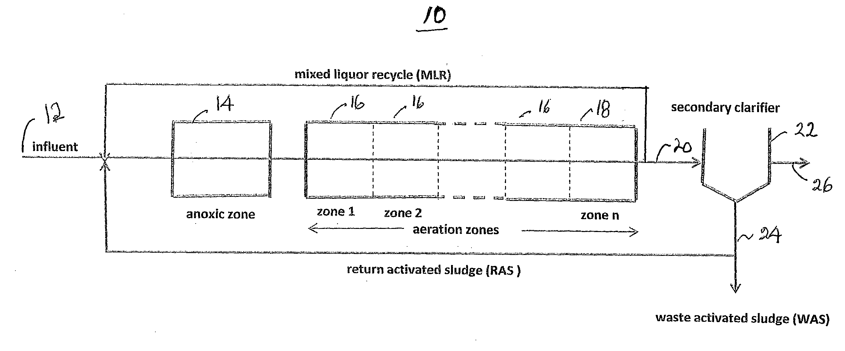
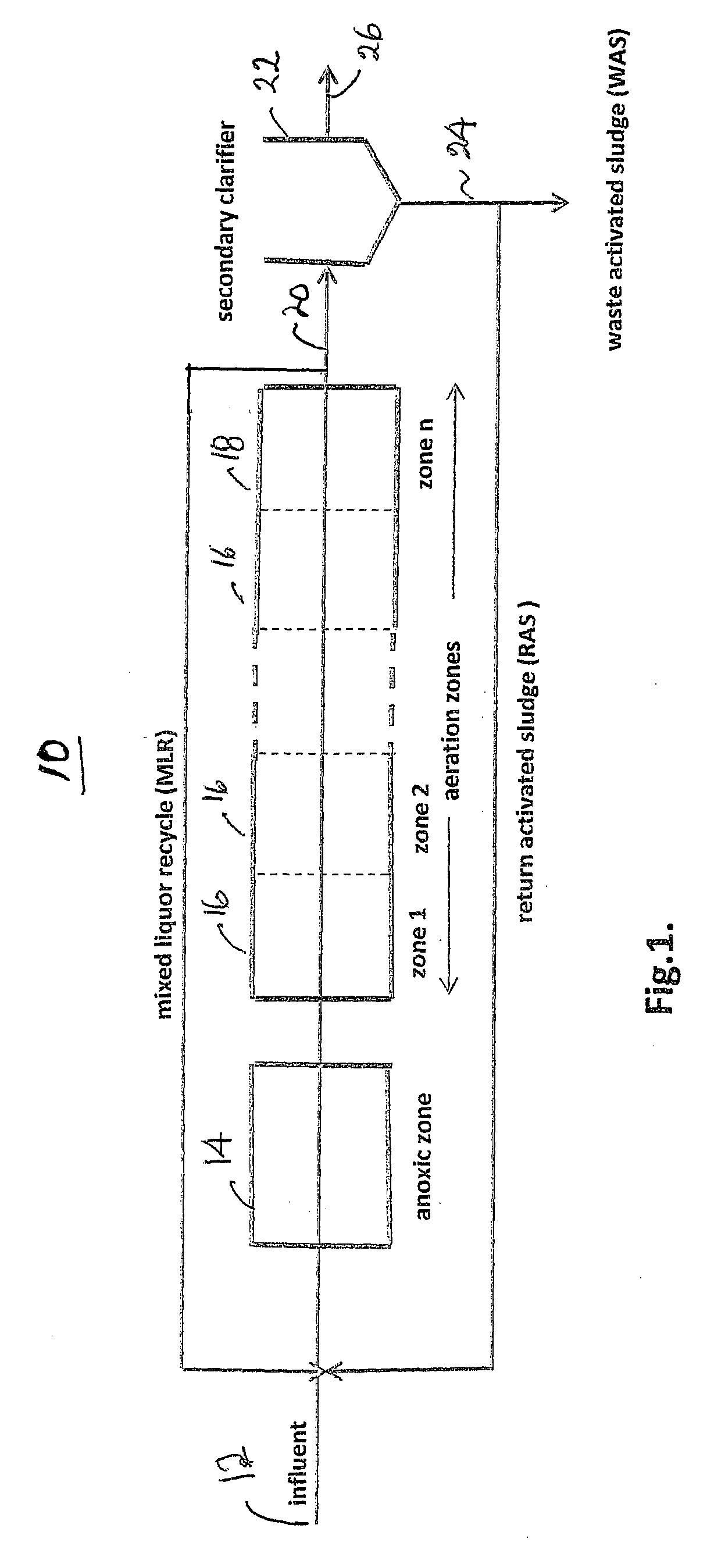
[0032]Referring now to the drawings and the illustrative embodiments depicted therein, an activated sludge wastewater treatment plant 10 is shown in FIG. 1. Waste is fed to an influent line 12 from an upstream supply, such as a primary clarifier effluent, and is supplied to a conventional anoxic zone 14. The effluent of zone 14 is supplied to a tandem series of aeration zones 16, which are designated zone 1, zone 2, . . . zone n in the direction of flow of the mixed liquor (primary effluent plus return activated sludge plus mixed liquor recycle). Each of the zones receives mixed liquor from an upstream zone and discharges mixed liquor to a downstream zone. In the aeration sections of an activated sludge process, air is bubbled through the mixed liquor. This provides the dissolved oxygen that certain species require in order to use the carbon compounds and ammonia present in the mixed liquor. The output 20 of final aeration zone 18 is recycled to influent line 12 in the form of mixed...


PUM


Abstract

A method and apparatus for operating an activated sludge plant having a plurality of tandem aeration zones, each receiving mixed liquor from an upstream zone or an upstream source and discharging a mixed liquor to a downstream zone or a downstream process includes a control which determines a parameter at a downstream one of the zones. The parameter is representative of a concentration of ammonia in the mixed liquor in the downstream one of the zones and may be used to control at least one upstream zone. A value of airflow to one of the zones may be determined and used to determine a demand for dissolved oxygen in the mixed liquor in that zone as a function of airflow to that zone. An elevated level of demand may be used to indicate a dump of commercial waste having a high BOD demand. A depressed level of demand may be used to indicate the presence of chemicals that inhibit bacterial respiration.

Description

BACKGROUND OF THE INVENTION[0001]The present invention is directed to an activated sludge plant and method for monitoring biological activity and controlling aeration in such a plant and, in particular, to such a plant being operated for ammonia removal.[0002]In the secondary process of a conventional activated sludge treatment plant, effluent from primary clarifiers is mixed with return activated sludge (RAS) to form mixed liquor. The mixed liquor consists of a suspension of flocs containing microbial species, which include heterotrophic and autotrophic bacteria. Both need oxygen in order to remove carbon and ammonia respectively from the surrounding solution. In the aeration section, high-volume low-pressure blowers are used to provide air to the aeration zones. Originally, blowers were turned on and a fixed volume of air was provided in an uncontrolled fashion. With the advent of dissolved oxygen (DO) sensors, instrument engineers recognized that the aeration system could be cont...

Claims


Application Information

Patent Timeline
IPC IPC(8): C02F3/12
CPCC02F3/006C02F3/121C02F2101/16C02F2209/38C02F2209/003C02F2209/14C02F2209/22C02F2209/001Y02W10/10C02F3/02
Inventor PALMER, DAVID G.
Owner PROCESS KINETICS
Learn More