
Foundation for a Wind Turbine Utilizing a Slurry of Low Viscosity Grout

a wind turbine and grout technology, applied in the field of concrete foundations, can solve problems such as damage to surrounding grout, and achieve the effect of reducing equipment and manpower and speeding up the erection of the turbin

Inactive Publication Date: 2012-11-22
TOOMAN NORMAN
View PDF3 Cites 25 Cited by
  • Summary
  • Abstract
  • Description
  • Claims
  • Application Information

AI Technical Summary

Benefits of technology

[0016]The present application is directed toward methods and apparatus which allow the utilization of a slurry of low viscosity, self-leveling grout, which results in a level surface for installing the base flange of a wind turbine tower. The self-leveling grout is placed within the foundation grout trough as an initial slurry having a viscosity at ambient temperature approximately the same as the viscosity of known grout slurries utilized in turbine foundations. After placement in the grout trough, elevated temperature is applied to the grout slurry, which lowers the viscosity of the slurry such that the slurry becomes self-leveling and the top surface assumes a nearly perfectly level surface. Additional elevated temperature is applied which initiates the curing of the grout to the required compressive strength for supporting the turbine tower.
[0017]A cover structure may be utilized in combination with the low viscosity grout slurry, where the cover structure may provide the heat transfer required to trigger the changes in the rheological properties of the grout slurry. The cover structure also provides protection from environmental conditions which might disturb the grout as is cures, such as rain, wind, hail, etc., and potentially disrupt the top surface of the grout.
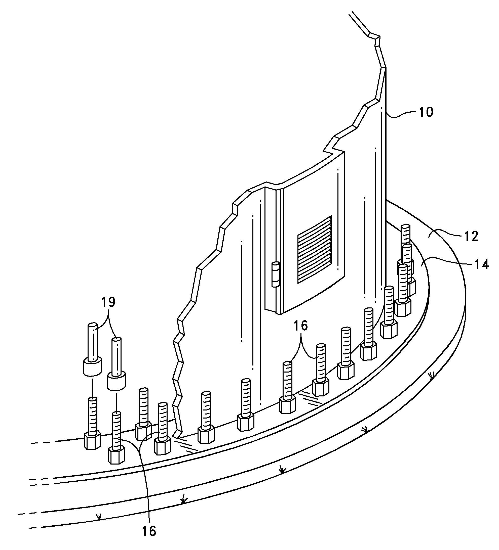
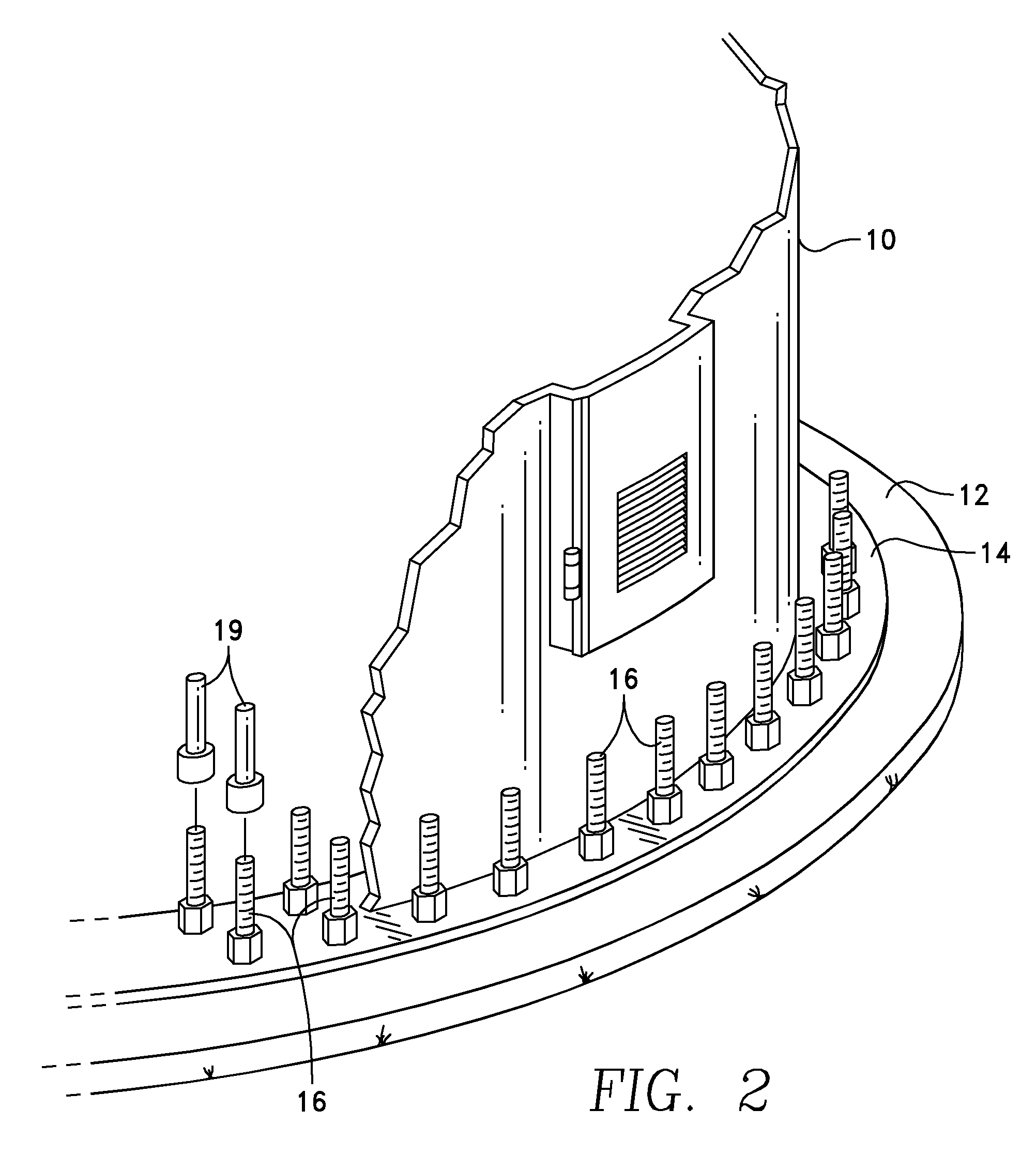
[0019]The use of the polypropylene sleeve and the swaging of the sleeve onto a portion of the bolt provides a bolt package (i.e. a bolt / sleeve combination) which has an overall diameter less than the overall diameter of the currently utilized bolt-PVC sleeve combination. This reduced diameter allows the bolt and crimped sleeve to extend through the bolt holes of the circular template, and into the bolt holes of the tower flange, which under the known apparatus and method, only a sleeveless bolt would extend. Because the crimped sleeve extends above the top of the grout trough, the encased bolts will not be exposed to water placed within the grout trough, or to a low viscosity grout slurry. In addition, because the top of the crimped sleeve extends above the level of the grout, the crimped sleeve prevents adhesion of the grout to the bolt, thereby allowing the bolt to move relative to the grout.
[0021]The advantage of the above procedure is that all of the turbine components can be installed with a single crane set, thereby speeding up the erection of the turbine while reducing the cost of equipment and manpower. In addition, utilization of the disclosed procedure allows the foundation bolts to be shortened by approximately eight inches each, which saves approximately $400 per installation.

Problems solved by technology

However, deformation of sealing member 32 reduces the ease with which anchor bolt 16 will slide through the sealing member, potentially causing sealing member 32 to also move, potentially damaging the surrounding grout 30.

Method used


Image

  • Foundation for a Wind Turbine Utilizing a Slurry of Low Viscosity Grout
  • Foundation for a Wind Turbine Utilizing a Slurry of Low Viscosity Grout
  • Foundation for a Wind Turbine Utilizing a Slurry of Low Viscosity Grout

Examples


Embodiment Construction

Prior Art Bolt Protection Devices

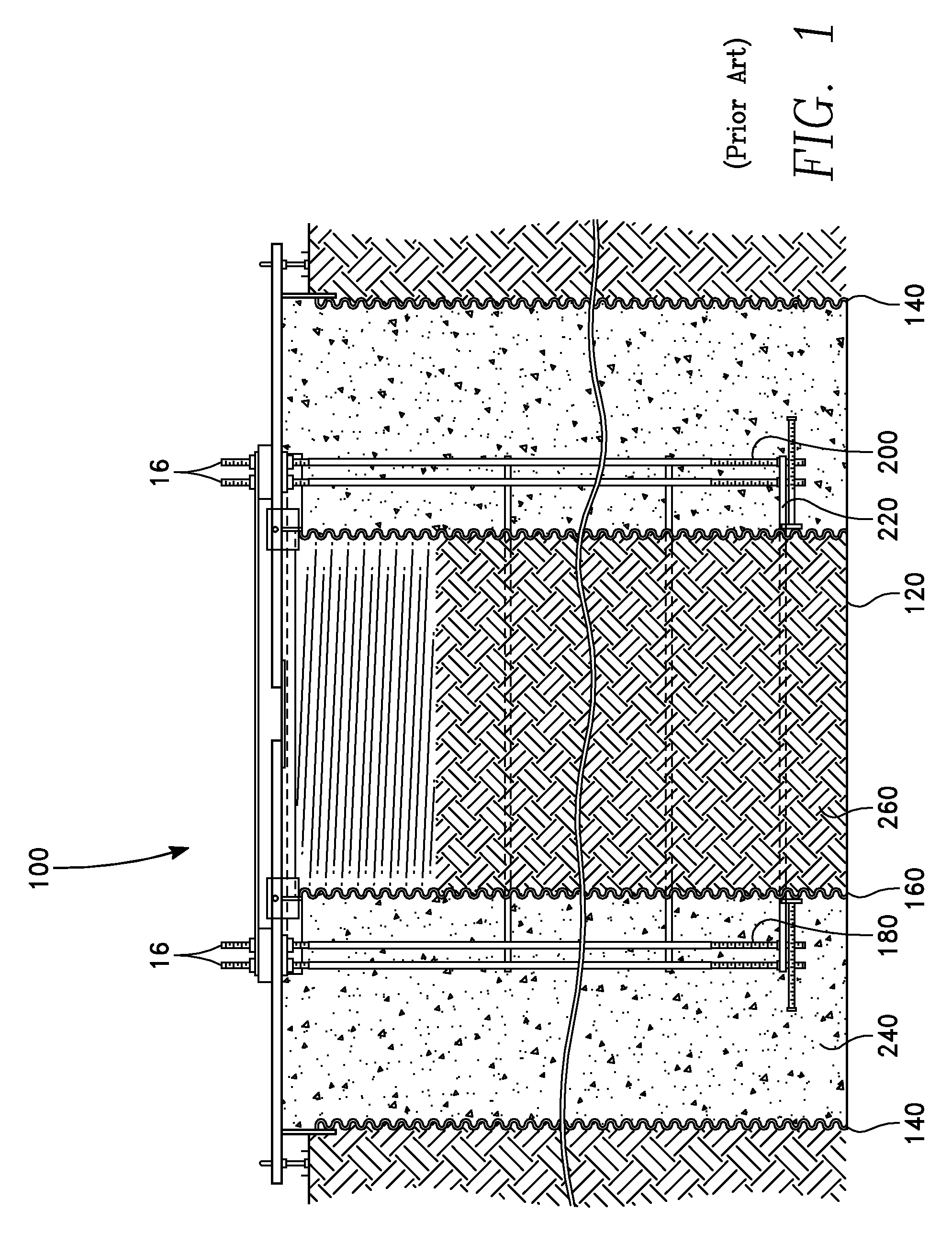
[0035]Referring specifically to the figures, FIG. 1 depicts an embodiment of a known foundation 100 utilized for installation of a relatively tall vertical structure, such as a wind turbine. It is to be appreciated that while the disclosed method and apparatus may be utilized to obtain a foundation 100 such as that depicted in FIG. 1, the procedure for obtaining the foundation is entirely different from the known methods. Foundation 100 comprises a bore hole 120, an outer boundary shell 140 and an inner boundary shell 160, each typically fashioned of corrugated metal pipe (“CMP”), set within the bore hole hole. An inner ring 180 of bolts 16 and an outer ring 200 of bolts 16 are disposed within the annulus formed between the outer boundary shell 140 and the inner boundary shell 160, with the bolts 16 anchored at the lower end of the bore hole 120 to an inbed plate 220. The annulus between the outer boundary shell 140 and the inner boundary shell 160 i...


PUM


Abstract

A self-leveling grout provides a level surface for the disposition of a wind turbine base. The self-leveling grout is placed within the foundation grout trough as an initial slurry having a viscosity at ambient temperature approximately the same as the viscosity of known grout slurries utilized in turbine foundations. After placement in the grout trough, elevated temperature is applied to the grout slurry, which lowers the viscosity of the slurry such that the slurry becomes self-leveling and the top surface assumes a nearly perfectly level surface. Additional elevated temperature is applied which initiates the curing of the grout to the required compressive strength for supporting the turbine tower.

Description

CROSS-REFERENCE TO RELATED APPLICATIONS[0001]U.S. Provisional Application No. 61 / 487,649 for this invention was filed on May 18, 2011, for which application this inventor claims domestic priority.BACKGROUND OF THE INVENTION[0002]This invention relates to concrete foundations set within excavations or bore holes which are installed to support wind turbines. More particularly, this invention comprises an apparatus and method for configuring, installing, and setting the anchor bolts for a cylindrical foundation for a wind turbine.[0003]U.S. Pat. Nos. 5,586,417 and 5,826,387, both by Henderson, disclose a foundation “which can be poured-on-site monolithically and is of cylindrical construction with many post-tensioned anchor bolts which maintain the poured portion of the foundation under heavy compression, even during periods when the foundation may be subject to high overturning moment.” Henderson's foundation is preferably in the shape of a cylinder, having an outer boundary shell and...

Claims


Application Information

Patent Timeline
Patent Type & Authority Applications(United States)
IPC IPC(8): E02D27/42E02D27/32E04G21/02
CPCE02D27/425E02D31/002
Inventor TOOMAN, NORMAN
Owner TOOMAN NORMAN
Learn More