
LED phosphor ink composition for ink-jet printing

a phosphor ink composition and inkjet printing technology, applied in the direction of biocides, inks, coatings, etc., can solve the problems of unintentionally uneven phosphor distribution, significant variability in phosphor distribution, and relatively difficult dispersibility of silicon, so as to prevent undesirable phosphor settling

Active Publication Date: 2012-11-15
HONG KONG APPLIED SCI & TECH RES INST
View PDF8 Cites 9 Cited by
  • Summary
  • Abstract
  • Description
  • Claims
  • Application Information

AI Technical Summary

Benefits of technology

[0010]The present invention provides an ink jet printable phosphor ink composition for LED packaging that enables precision control of the amount and position of phosphor layers on the LED device or the LED device packaging. The ink includes both a UV-curable resin component and a thermally curable resin component. A phase-separation component prevents phase separation of the UV-curable resin component and the thermally curable resin component. Phosphor particles on the order of less than approximately 2 microns are uniformly dispersed throughout the ink composition. To ensure ink jetting ability of the ink by ink jet printers, the ink viscosity is maintained below approximately 50 centipoise.
[0012]Due to the unique nature of the phosphor inks of the present invention, the phosphor amount and distribution can be precisely controlled through ink jet printing. The phosphor ink composition is deposited through either thermal or piezoelectric ink jet printing either directly on an LED die or on an LED package such as a silicone or epoxy package. A layer approximately 5 microns thick is deposited in a desired pattern. UV curing is used to fix the layer, with optional thermal curing, followed by subsequent deposition and curing. Alternatively, thermal curing is performed following deposition of all the phosphor layers. In this manner, the phosphor particle positions are fixed in each layer, preventing undesirable phosphor settling. The layers are selectively built up to form precise amounts of phosphors across the LED or LED package.

Problems solved by technology

Various challenges exist in producing a LED with a high luminous output that is suitable for use as a light source in human environments.
Silicone, however, is relatively harder to dispense.
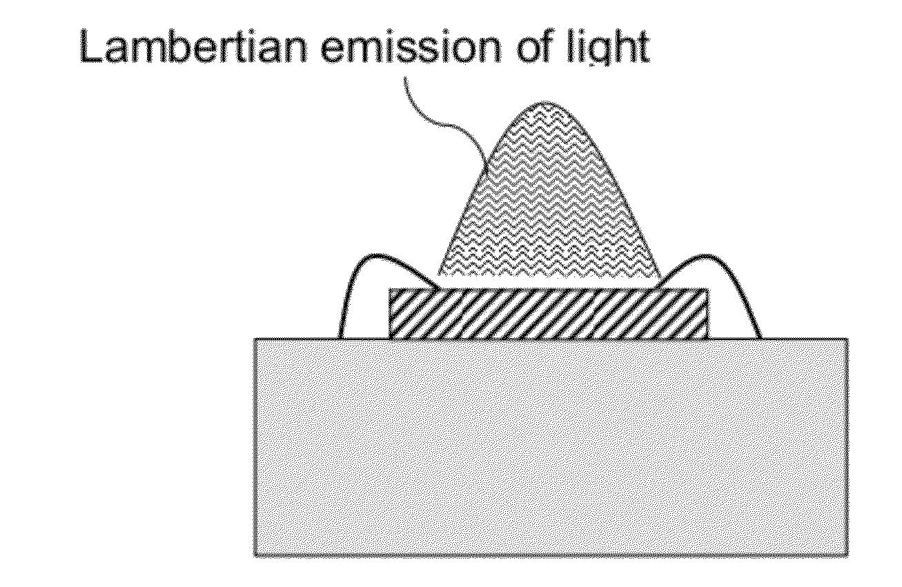
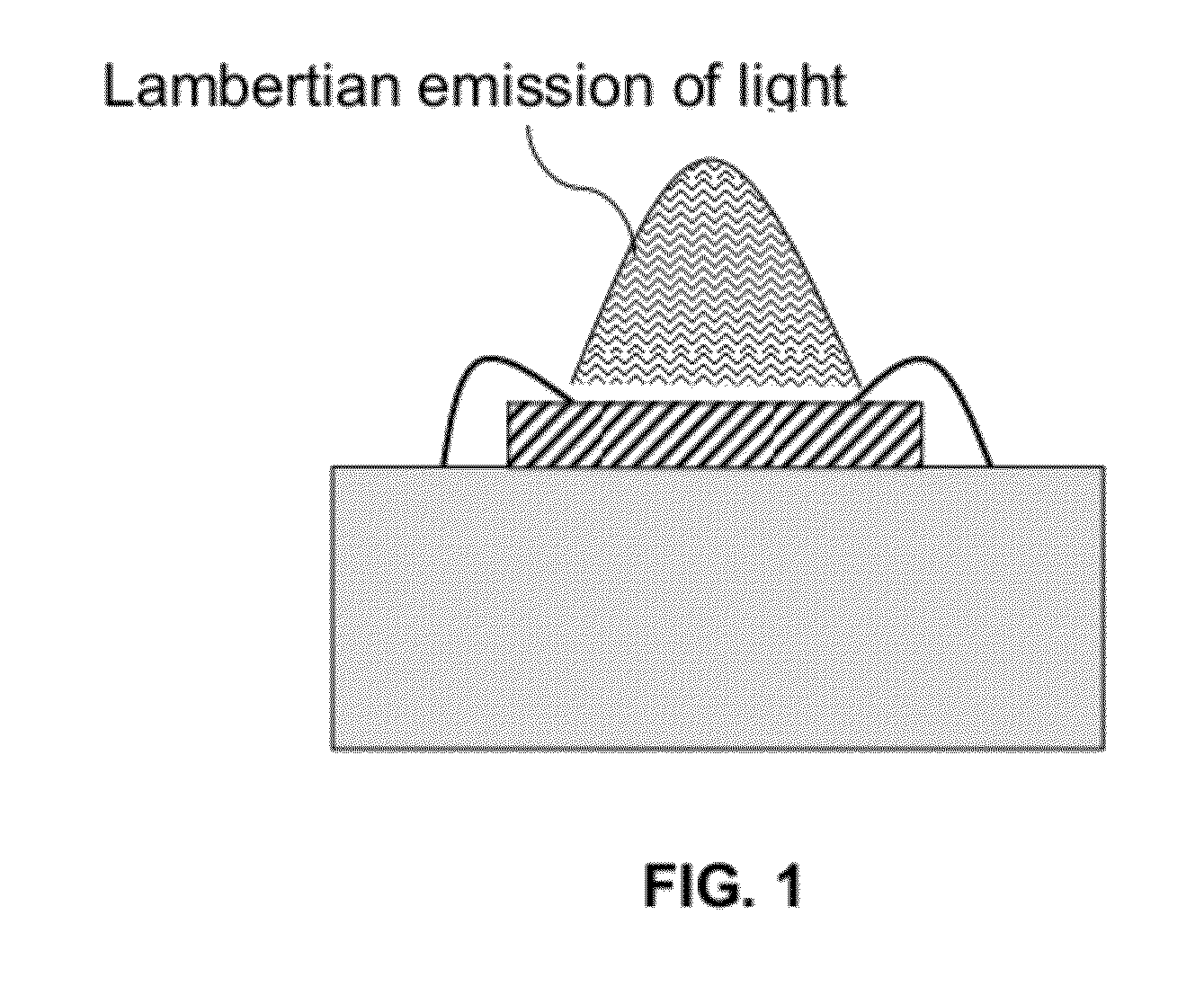
When the phosphor is dispersed within the encapsulating material, process control issues can result in unintentionally uneven phosphor distribution in unpredictable patterns surrounding the LED.
Current techniques for applying phosphors result in significant variability in phosphor distributions due to thickness variations in the encapsulant and uneven distribution and / or settling of phosphors during curing.
Further, many devices are rejected as not conforming to specifications due to manufacturing issues.

Method used


Image

  • LED phosphor ink composition for ink-jet printing
  • LED phosphor ink composition for ink-jet printing

Examples


example 1

[0020]Example 1 presents phosphor ink compositions according to the present invention.

CompositionMaterialRangeclassExamples(weight %)PhosphorYAG: Ce, SrBaSiEu, CaS: Eu, 3-18YAG: Tb, SrS: Eu, SrGa2S4: EuHydroxy-Glycerol 1,3-diglycerolate 1-15functionaldiacrylate, Sartomer CN132,acrylicCN120, CN133monomerPhotoinitiatorIrgacure 819DW, 29590.05-1.0 Epoxy CureKing Industries CXC1615,0.05-1.0 Cat.1735, 1612EpoxyGlycerol triglycidylether 2-15monomerHumectantsGlycerol, Dipropylene glycol,10-30diethylene glycol, ethylene glycolCosolventsGamma-Butyrolactone, N-Methyl-10-30pyrrolidone, N-vinylpyrrolidinone*,n-vinyl caprolactam*, n-vinylacetamide*BiocideProxel GXC0.1-1.0SurfactantsSilwet 7001, 7230, 76050.05-3  Water30-80*Reactive diluents


PUM

PropertyMeasurementUnit
viscosityaaaaaaaaaa
thickaaaaaaaaaa
thicknessaaaaaaaaaa

Abstract

The present invention provides an ink jet printable phosphor ink composition for LED packaging that enables precision control of the amount and position of phosphor layers on the LED device or the LED device packaging. The ink includes both a UV-curable resin component and a thermally curable resin component. A phase-separation component prevents phase separation of the UV-curable resin component and the thermally curable resin component. Phosphor particles on the order of less than approximately 2 microns are uniformly dispersed throughout the ink composition. The phosphor ink composition is deposited through either thermal or piezoelectric ink jet printing; a thin layer is deposited in a desired pattern. UV curing (and, optionally, thermal curing) is used to fix each layer followed by subsequent deposition and curing. In this manner, undesirable phosphor settling does not occur and layers are selectively built up to form precise phosphor distributions.

Description

TECHNICAL FIELD[0001]The present invention relates generally to phosphor inks for LEDs. In particular it relates to phosphor inks for ink jet printing precision phosphor quantities on LEDs and / or LED packaging.BACKGROUND[0002]A light emitting diode (“LED”) is a semiconductor light source. LEDs provide numerous advantages over other light sources such as incandescent lights. Amongst other advantages, LEDs typically have longer lifetimes, greater reliability, faster switching characteristics and lower energy consumption. Recent advances have produced LEDs with luminous intensities (lumen per Watt) that are comparable with or surpass incandescent lights.[0003]LEDs produce light by the spontaneous recombination of electron and hole pairs when the LED is forward biased above the threshold voltage in an electronic circuit. The wavelength of the light produced depends upon the band gap between the materials used in the p-n junction that form the LED. The wavelength of the light produced by...

Claims


Application Information

Patent Timeline
Patent Type & Authority Applications(United States)
IPC IPC(8): H01L33/50C08J3/28C09D11/10
CPCC09K11/025C09D11/322C09D11/101H01L2933/0041C09K11/08H01L2224/48091H01L2924/00014
Inventor MCKEAN, DENNIS
Owner HONG KONG APPLIED SCI & TECH RES INST
Learn More