
Seismic true estimated wavelet

a true estimated wavelet and seismic technology, applied in the field of seismic exploration, can solve the problems of a large number of spikes, high cost of seismic surveying, and much effort in improving the efficiency of seismic surveying

Active Publication Date: 2012-11-15
CONOCOPHILLIPS CO
View PDF2 Cites 14 Cited by
  • Summary
  • Abstract
  • Description
  • Claims
  • Application Information

AI Technical Summary

Benefits of technology

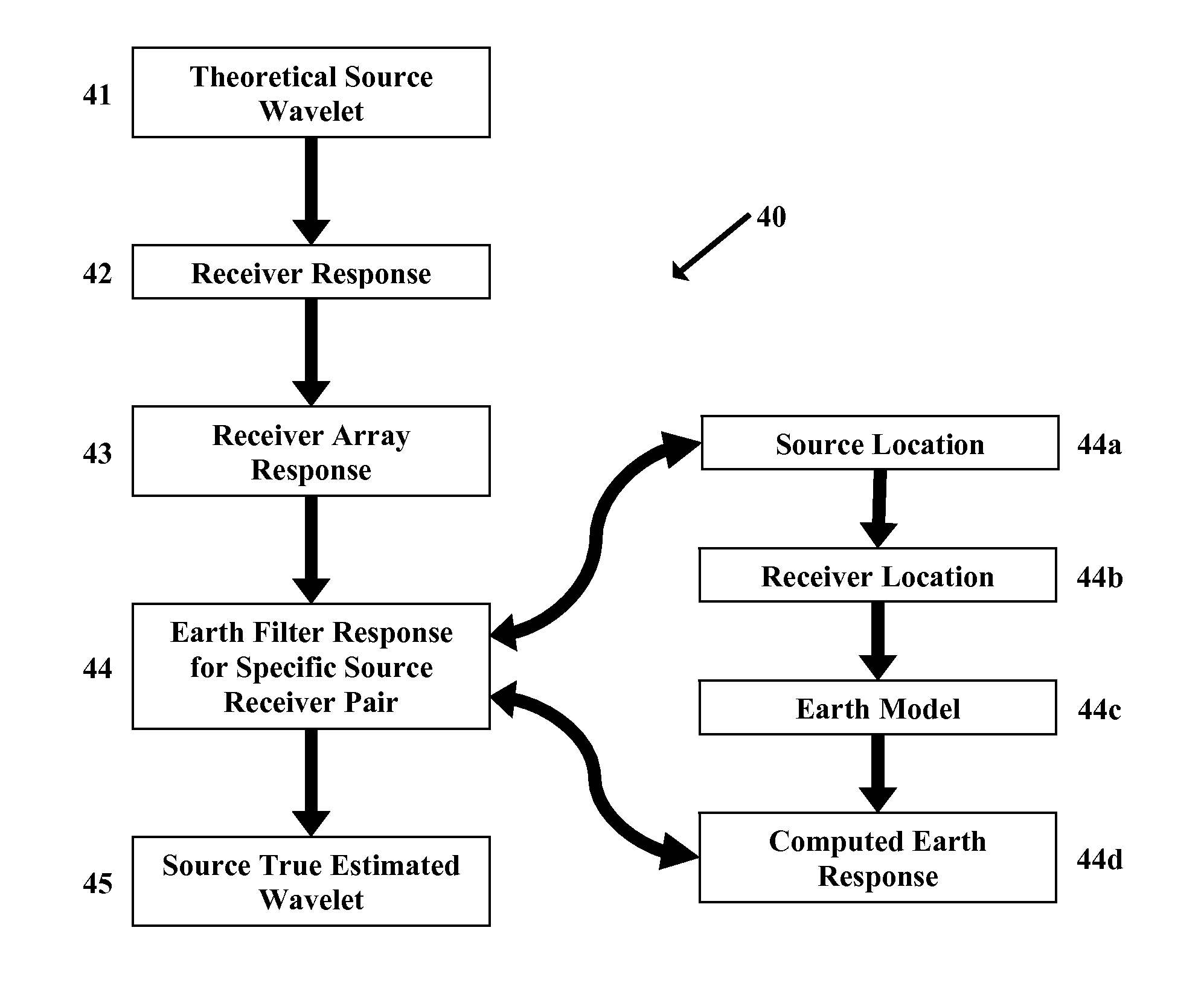
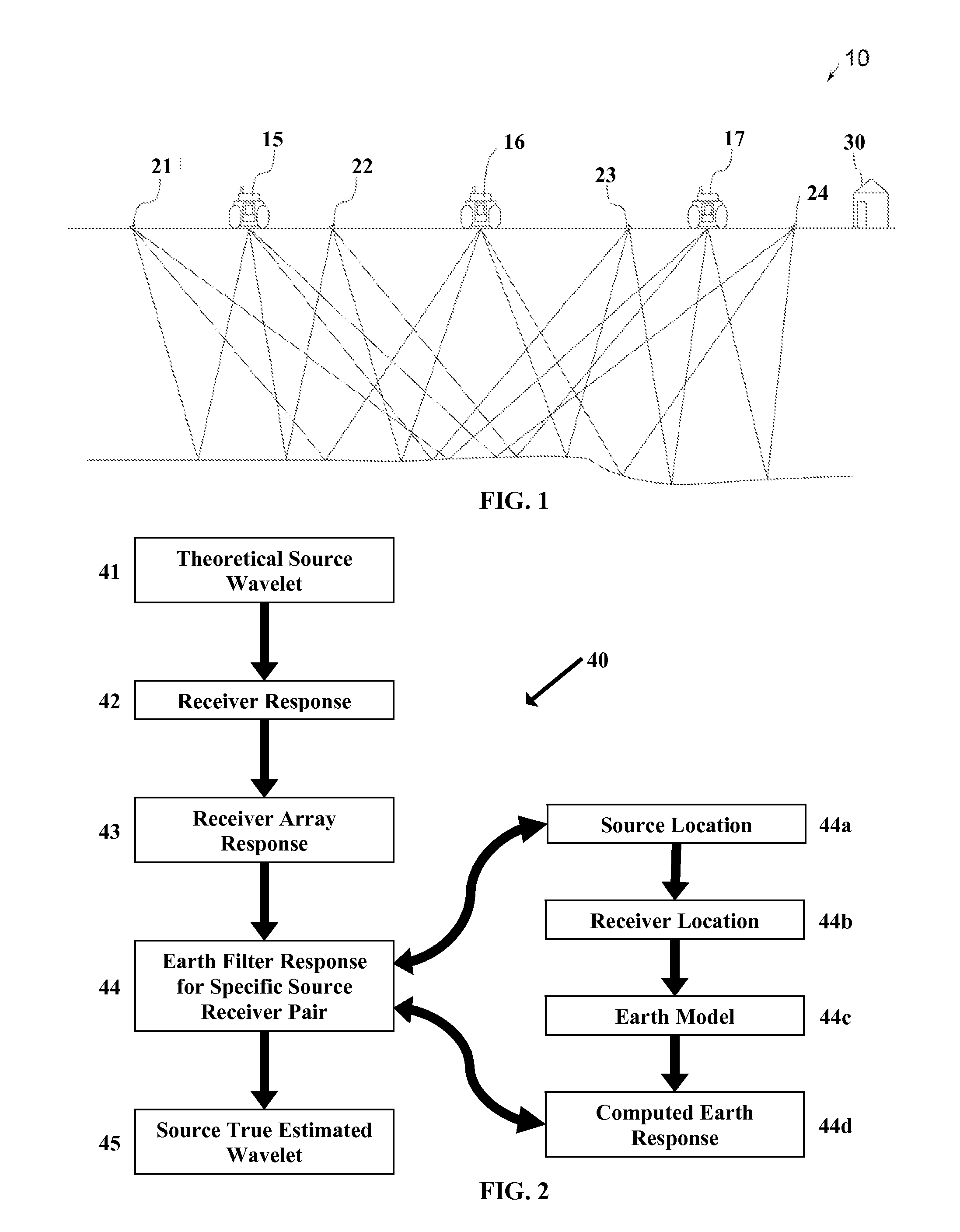
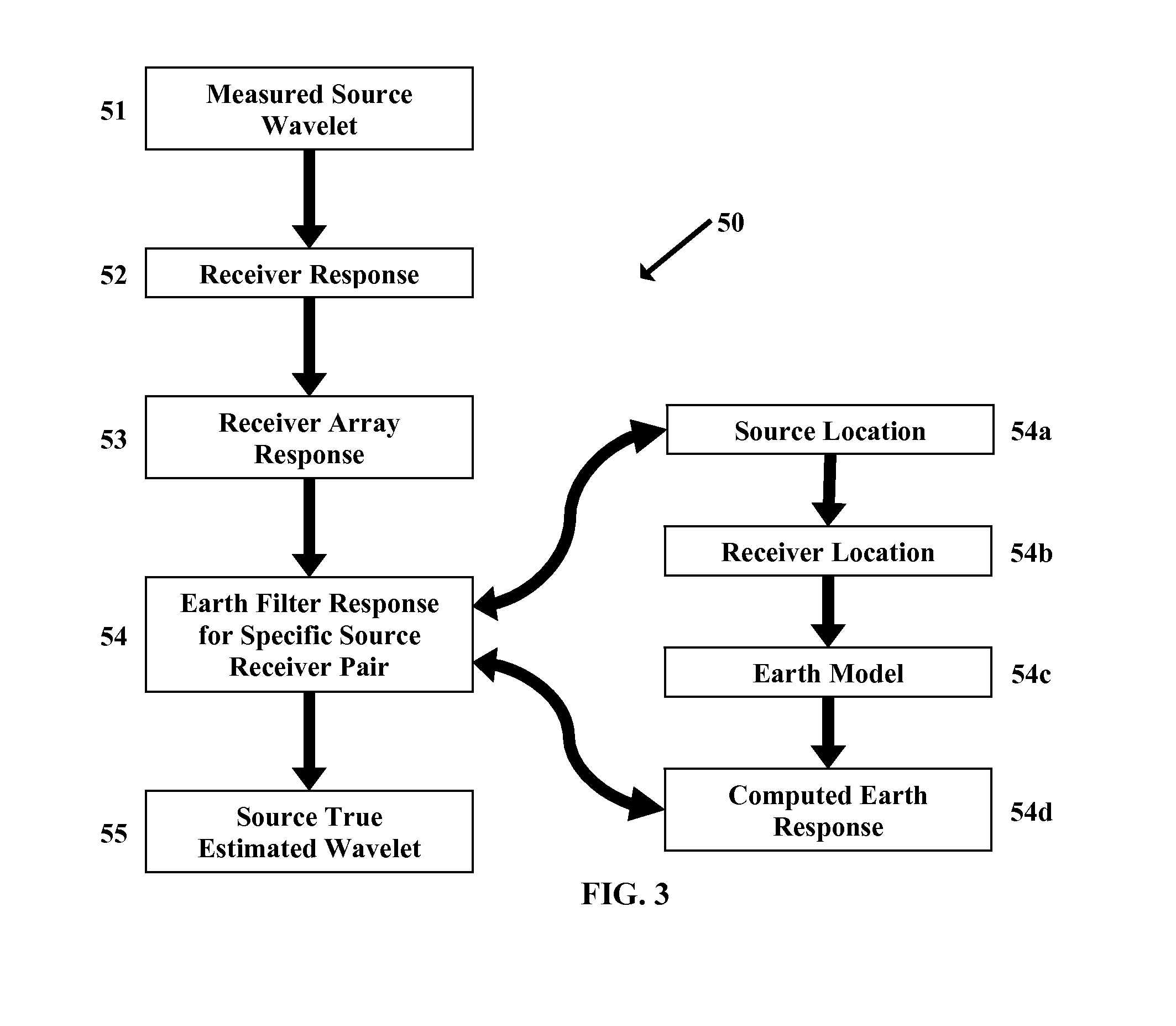
[0012]The invention more particularly relates to a method of optimizing the separation of composite seismic data that includes signals from two or more seismic sources. The method more particularly includes the acquisition of seismic data to create a data set for a survey area. An initial source wavelet is identified and an expected response to the initial source wavelet by one or more seismic receivers taking into consideration the geometric relationship of the receivers to the source is identified. A computed earth response is created for each source and receiver pair based on the geology between the source and receiver and the computed earth response is applied to the expected response to the initial source wavelet to create a source true estimated wavelet for each source receiver pair. The source true estimated wavelet is then used for at least one further processing step of the acquired data set such as inverting, separating, de signaturing or wavelet de convolving.

Problems solved by technology

A routine seismic survey will create a tremendous number of spikes.
However, it is more common to use similar sources throughout a survey, where the distinguishing characteristics of individual sources are typically not highly distinctive.
The costs for a seismic survey can be quite expensive and much effort has gone into improving the efficiency of seismic surveying.
With distinctive and identifiable sweeps, the problem then becomes one of time and effort efficiency for separating out the individual shot records from the composite data set.
The problem is that the true vibe source signal is not precisely known.
This leads to imperfect separation and poor resultant separated data.

Method used


Image

  • Seismic true estimated wavelet
  • Seismic true estimated wavelet
  • Seismic true estimated wavelet

Examples


Embodiment Construction

[0018]Turning now to the detailed description of the preferred arrangement or arrangements of the present invention, it should be understood that the inventive features and concepts may be manifested in other arrangements and that the scope of the invention is not limited to the embodiments described or illustrated. The scope of the invention is intended only to be limited by the scope of the claims that follow.

[0019]This invention relates to a process to separate simultaneously or near simultaneously activated seismic data sources where the separation method requires as one component that the seismic source signature be uniquely or distinctly coded in some manner. This includes data that comprises signals from at least two sources and typically three or four sources where source separation is necessary for geophysical analysis. Specifically, the present invention is a realization that the wavelet viewed by each seismic signal sensor location or receiver location is a function of th...


PUM


Abstract

The invention relates to processing seismic data that includes signals from at least two sources and typically three or four sources where source separation is necessary for geophysical analysis. Specifically, the present invention is a process for correcting data prior to inversion where the correction is provided to correct for the filtering effect of the earth. The earth is a non-homogenous seismic propagator that causes distortions of wavelets of seismic energy related to the source and receiver azimuth and offset that makes the identification of source specific data within the composite data harder to identify. Computing an earth response and correcting for the effects of the earth on the wavelets provides for more resolution and more clarity in the resulting data and better geophysical interpretation.

Description

CROSS-REFERENCE TO RELATED APPLICATIONS[0001]This application is a non-provisional application which claims benefit under 35 USC §119(e) to U.S. Provisional Application Ser. No. 61 / 486,022 filed May 13, 2011, entitled “ SEISMIC TRUE ESTIMATED WAVELET,” which is incorporated herein in its entirety.STATEMENT REGARDING FEDERALLY SPONSORED RESEARCH[0002]None.FIELD OF THE INVENTION[0003]This invention relates to seismic exploration and particularly to processing seismic data created by recording seismic energy received by seismic receivers based on energy input into the ground using seismic sources.BACKGROUND OF THE INVENTION[0004]There are a variety of source types for delivering seismic energy into the earth. Each type of seismic source provides seismic energy that has common characteristics that can be observed in the data record. However, it is generally desired that seismic sources used in a survey are operable to create distinguishable characteristics so that the data record may be...

Claims


Application Information

Patent Timeline
Patent Type & Authority Applications(United States)
IPC IPC(8): G01V1/36
CPCG01V1/37G01V2210/127G01V2210/58
Inventor EICK, PETER M.BREWER, JOEL D.
Owner CONOCOPHILLIPS CO
Learn More