
Touch apparatus and touch sensing method thereof

a technology of touch apparatus and touch sensing device, which is applied in the direction of instruments, computing, electric digital data processing, etc., can solve the problems of power waste, and achieve the effect of effectively removing low frequency nois

Inactive Publication Date: 2012-11-15
HIMAX TECH LTD
View PDF8 Cites 14 Cited by
  • Summary
  • Abstract
  • Description
  • Claims
  • Application Information

AI Technical Summary

Benefits of technology

[0007]The invention is directed to a touch apparatus and a touch sensing method thereof, which can effectively remove low frequency noises in sensing signals, for example, finger noises or low frequency noises caused by other touch objects.
[0021]In an embodiment of the invention, the touch apparatus further includes a plurality of third touch units, and the method for eliminating noise of the touch apparatus further includes following steps. The third touch units are respectively driven during different line scan periods. The third touch units are respectively detected through the sensing line during the different line scan periods to obtain a plurality of third original signals. The reference signal is obtained according to the second original signal and the third original signals.
[0024]According to the above descriptions, the touch units on the scan line are detected during different scan periods to obtain the first original signal and the second original signal, and the reference signal is obtained according to the second original signal. Then, the reference signal is subtracted from the first original signal to eliminate the low frequency noise of the first original signal, so as to obtain the sensing signal of the first touch unit. In this way, correctness of determining the touch position is improved.

Problems solved by technology

Since the capacitive touch apparatus is liable to be influenced by environment variations, for example, low frequency noises generated when the finger or other objects touch the touch apparatus, the electronic device may have misjudgement to cause waste of power.

Method used


Image

  • Touch apparatus and touch sensing method thereof
  • Touch apparatus and touch sensing method thereof
  • Touch apparatus and touch sensing method thereof

Examples


Embodiment Construction

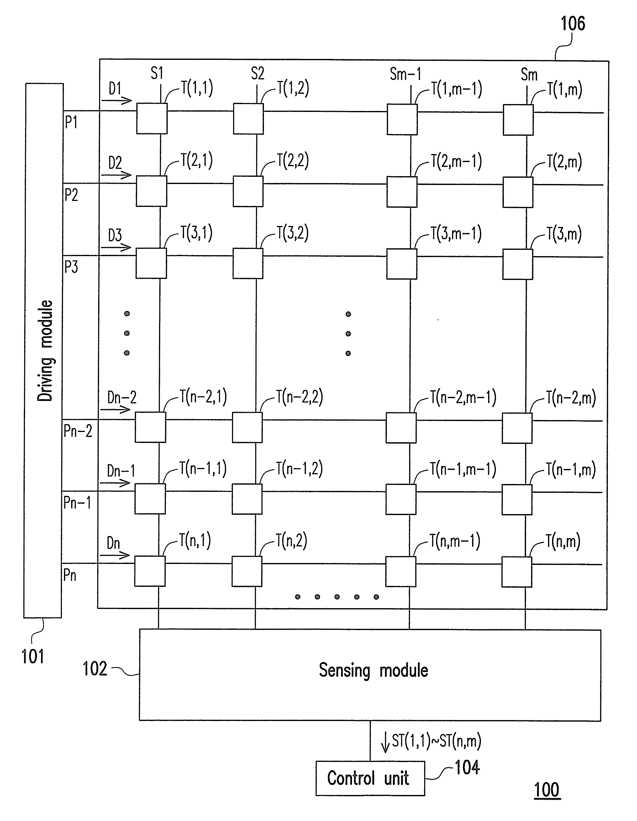
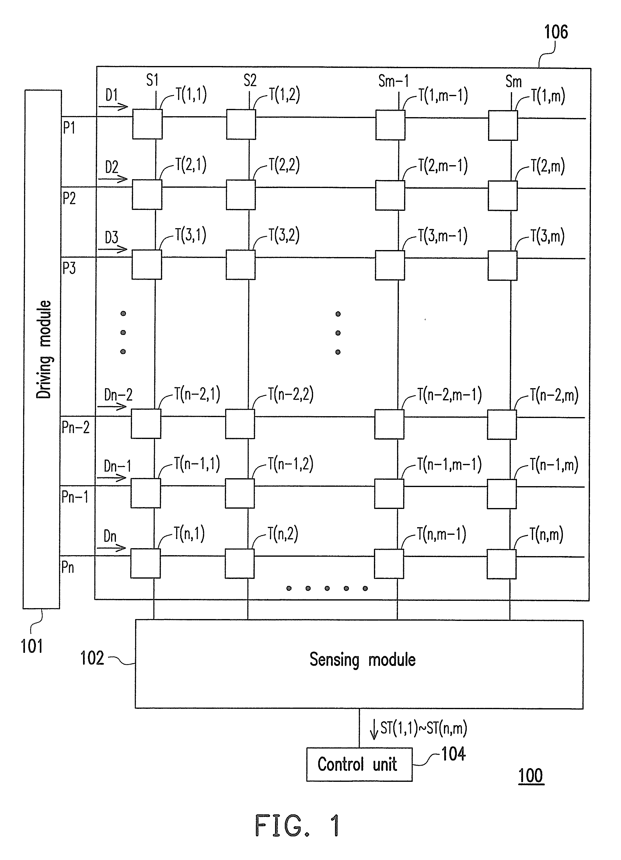
[0031]FIG. 1 is a schematic diagram of a touch apparatus according to an embodiment of the invention. Referring to FIG. 1, the touch apparatus 100 includes n scan lines P1-Pn, m sensing lines S1-Sm, a plurality of touch units T(x,y), a driving module 101, a sensing module 102 and a control unit 104. The scan lines P1-Pn and the sensing lines S1-Sm are disposed on a touch panel 106, and the touch unit T(x,y) represents a touch unit located at an intersection of an xth scan line and a yth sensing line, where n, m, x and y are positive integers, and 1≦x≦n, 1≦y≦m. Moreover, the sensing module 102 is coupled to the sensing lines S1-Sm and the control unit 104.

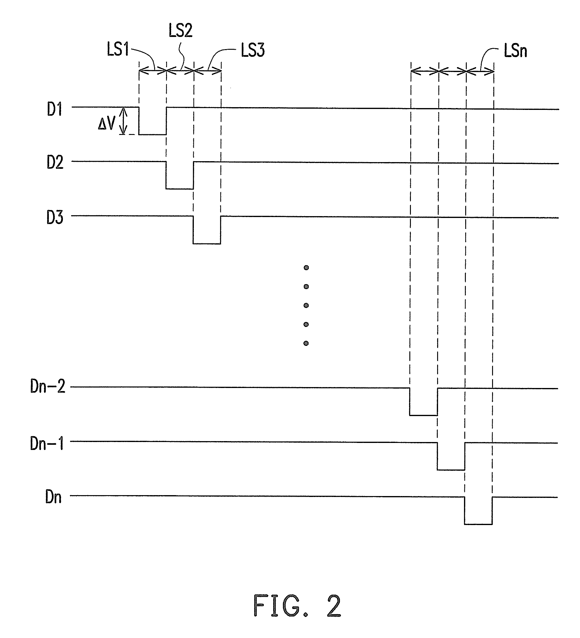
[0032]The touch units T(x,1) on the sensing line S1 may respectively receive driving signals D1-Dn and can be driven during different line scan periods. For example, FIG. 2 is a waveform diagram of driving signals of the scan lines P1-Pn according to an embodiment of the invention. Referring to FIG. 2, a low level period of each of ...


PUM


Abstract

A touch apparatus and a touch sensing method thereof are provided. The touch sensing method includes the following steps. A first touch unit and a second touch unit are detected at different scan periods to obtain a first original signal and a second original signal. A reference signal is obtained according to the second original signal. A subtraction is performed on the first original signal and the reference signal, so as to eliminate low frequency noise of the first original signal.

Description

BACKGROUND[0001]1. Field of the Invention[0002]The invention relates to a touch apparatus and a touch sensing method thereof. Particularly, the invention relates to a touch apparatus capable of removing low frequency noises and a touch sensing method thereof.[0003]2. Description of Related Art[0004]A touch panel or a touch pad is generally integrated with a portable information product to achieve a more user-friendly user interface. Related panel manufacturers and IC design companies all take the touch panel technique as a major research and development project, and the related techniques and products have been applied to daily used electronic products such as information products of mobile phones, computers and personal digital assistants, etc.[0005]The commonly used touch apparatus are divided into resistive touch apparatus and capacitive touch apparatus. A main operation principle of the capacitive touch apparatus is to sense an electrical characteristic of capacitance. When two ...

Claims


Application Information

Patent Timeline
Patent Type & Authority Applications(United States)
IPC IPC(8): G06F3/041
CPCG06F3/044G06F3/0418G06F3/04186G06F3/0446
Inventor CHENG, JEN-WEN
Owner HIMAX TECH LTD
Learn More