
White LED lighting device, and optical lens

a technology of led lighting and optical lens, which is applied in the direction of lighting and heating apparatus, semiconductor devices for light sources, instruments, etc., can solve the problems of inability to obtain well-looking and uniform light as illumination light, color separation and unevenness of emission light, and a little power consumption

Inactive Publication Date: 2012-11-15
NITTO OPTICAL CO LTD +1
View PDF2 Cites 10 Cited by
  • Summary
  • Abstract
  • Description
  • Claims
  • Application Information

AI Technical Summary

Benefits of technology

[0014]The techniques described in PTL1 and PTL2 effectively function when an area of a LED light emitting portion is sufficiently small compared to a lens.
[0016]The present invention is made in light of this situation, and an object of the present invention is to provide a white LED lighting device and an optical lens which can reduce unevenness in color of illumination light.Solution to Problem
[0025]According to the present invention, it is possible to provide a white LED lighting device and an optical lens which can reduce unevenness in color of illumination light.

Problems solved by technology

However, light sources are desired which consume a little power and take current environment issues such as reduction in CO2 into account.
However, when a condenser lens is embedded in a LED package formed with a LED chip mounted on a body and a wavelength converting member arranged on an upper part of this LED chip, color separation and unevenness in color of emission light caused by a light emitting configuration of a LED package are produced.
As a result, unevenness in color which is observed particularly as a state where a strong yellow tinge is emitted in a peripheral rim area of illumination light is produced, and well-looking and uniform light cannot be obtained as illumination light.
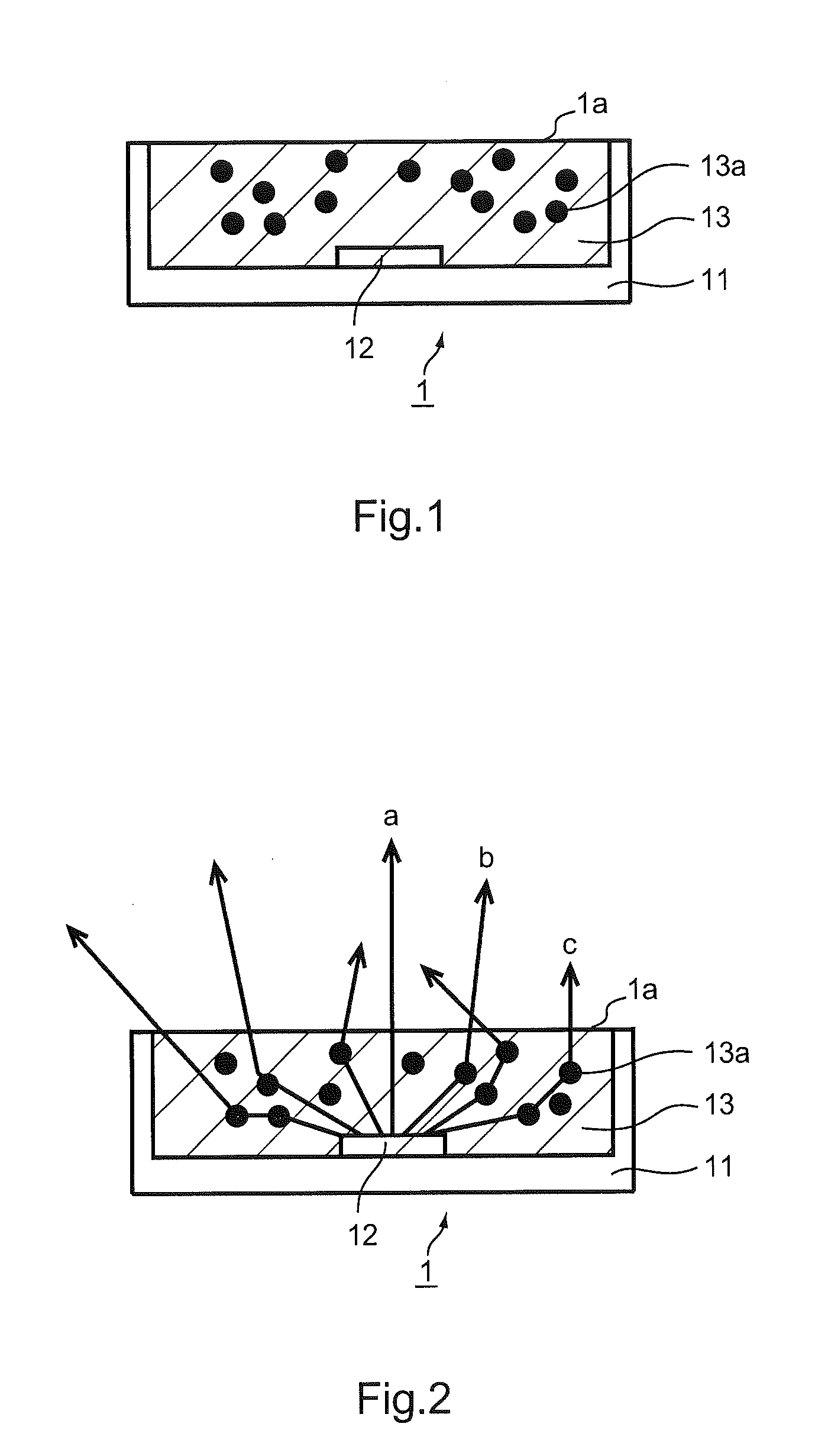
Further, a LED structure which uses a yellow fluorescent material for a blue light emitting element has, in a directly upward direction and a circumferential direction of a light emitting element, different rates that light is converted into yellow in a fluorescent material based on a relationship of a light route through which light passes to be radiated, and has a structural problem that unevenness in color is also observed from radiation light.

Method used


Image

  • White LED lighting device, and optical lens
  • White LED lighting device, and optical lens
  • White LED lighting device, and optical lens

Examples


modified example

[0117]1. In addition, although scattering fine particles of a single particle diameter are selected as described above, the present embodiment is by no means limited to this, scattering fine particles of a plurality of particle diameters may be mixed and used.

[0118]2. Further, as described above, by selecting scattering particle diameters which is near 3.6 μm at which the scattering efficiency Q(B) of blue light significantly exceeds the scattering efficiency Q(R) of red light and blue light is more strongly scattered than red light, unevenness in color temperature and unevenness in color tone of pale blue in the center portion of radiation light and white tinged with yellow in the peripheral portion. However, in addition to scattering particle diameters, other diameters (for example, particle diameters between 2 and 4.5 μm) may be used as long as they are equal to 5 μm or less with the example in FIG. 3A and FIG. 3B. Meanwhile, it is more effective when the ratio of the scattering ...


PUM


Abstract

Disclosed are a white LED lighting device and an optical lens used in it. The white LED lighting device comprises a white LED and an optical lens. The white LED includes: a LED chip which emits blue light: and a fluorescent material which is excited by emission light of the LED chip and converts a wavelength into fluorescence of a complementary color of blue. The optical lens is formed with a scattering light guide which is given uniform scattering power in terms of a volume. The scattering light guide includes scattering particles for the scattering efficiency in a short wavelength range of light to be higher than that in a long wavelength range of light.

Description

CROSS-REFERENCE TO RELATED APPLICATIONS[0001]The present application is a national phase of an International application No. PCT / JP2010 / 050006 filed on January, 2011, which relates to and claims priority from Japanese patent application No. 2010-008626 filed on Jan. 19, 2010. The contents of the International application and the Japanese application are incorporated herein by reference.TECHNICAL FIELD[0002]The present invention relates to a white LED lighting device and an optical lens and, more particularly, relates to a white LED lighting device and an optical lens which can reduce unevenness in color of illumination light.BACKGROUND ART[0003]Incandescent lamps and fluorescent lamps are widely used as common lighting devices. However, light sources are desired which consume a little power and take current environment issues such as reduction in CO2 into account. As light sources which meet this demand, LEDs (Light Emitting Diodes) are gaining attention in recent years.[0004]By the...

Claims


Application Information

Patent Timeline
IPC IPC(8): H01L33/50
CPCF21V5/04G02B19/0014G02B19/0061F21Y2101/02H01L33/58H01L2933/0091G02B19/0028H01L33/50F21Y2115/10
Inventor SHINOHARA, YOSHINORIKOIZUMI, FUMIAKI
Owner NITTO OPTICAL CO LTD
Learn More