
Solar panel system and methods of passive tracking

a solar panel and passive tracking technology, applied in the field of solar panels, can solve the problems of not providing bi-directional tracking of solar panels or groups of solar panels, prone to wind damage, and certain disadvantages of conventional solar tracking systems

Active Publication Date: 2012-11-15
SURGANOV ANTHONY
View PDF4 Cites 35 Cited by
  • Summary
  • Abstract
  • Description
  • Claims
  • Application Information

AI Technical Summary

Benefits of technology

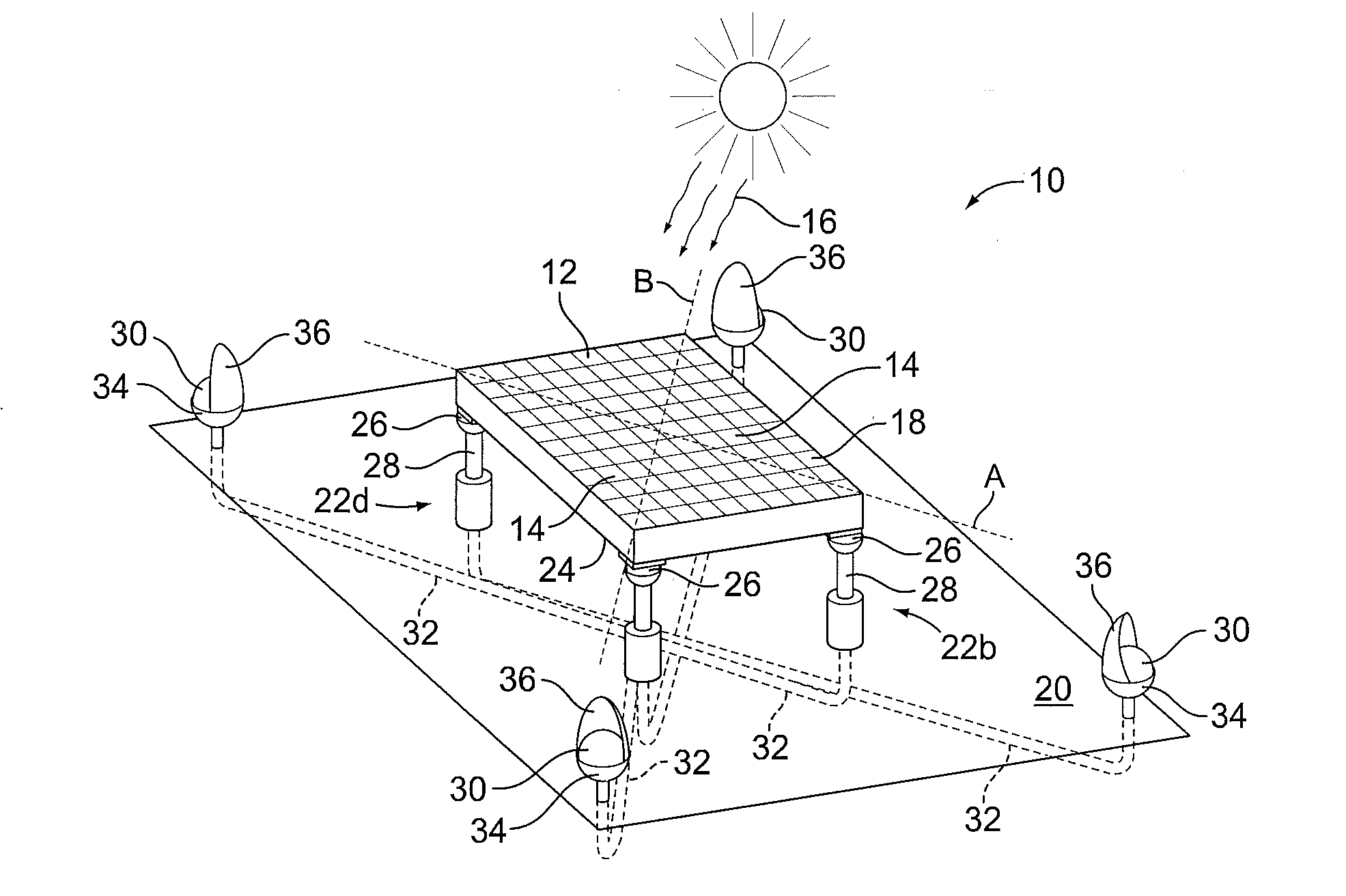
[0007]Preferred embodiments of the present invention include a solar panel system and methods for providing passive solar tracking. Embodiments of the present invention permit bi-directional movement of the solar panel while providing an improved support mechanism to protect the solar panel such as from wind, rain, damage and debris.
[0009]Embodiments of the solar panel have a front face and a back face. In certain embodiments, the front face is positioned to receive solar illumination from the sun or another light source. In certain embodiments, the back face is connected to the plurality of lift assemblies. The solar panel may be oriented using a passive rotation arrangement to permit a maximum amount of solar illumination to impinge perpendicularly on the front face of the solar panel. Advantageously, the amount of solar energy collected in the solar panel may be improved as more rays of solar illumination impinge perpendicularly on a face of a solar panel, compared to when rays of solar illumination impinge non-perpendicularly.
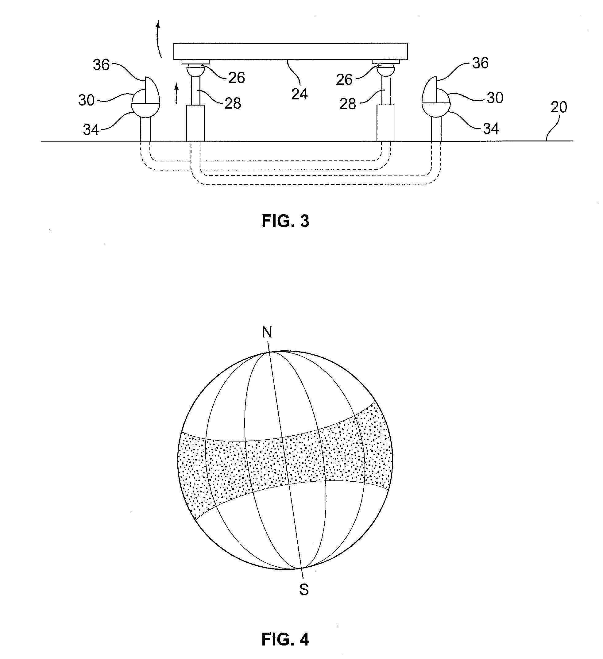
[0010]Embodiments of the lift assemblies may include a piston that expands and contracts to raise and lower the solar panel at one of the cardinal points which rotates the solar panel about one of longitudinal and lateral axes. Accordingly, activation of more than one piston may rotate passively and bi-directionally the solar panel about the axes to maximize solar illumination that impinges perpendicularly to the front face of the solar panel. This solar energy captured by the solar panel is increased as compared to conventional passive solar tracking systems. Moreover, the connection of the piston assemblies to the four cardinal points at the back side of the solar panel improves structural support for the solar panel to protect against wind damage.
[0012]In certain embodiments, a solar illumination sensor and conduit may also be included as part of the lift assemblies. The conduit connects the solar illumination sensor to the piston. Fluid is contained in the solar illumination sensor and conduit which may be heated to activate and extend the piston to rotate the solar panel about one of the axes. The solar illumination sensor may include a canister that receives solar illumination directly and / or indirectly from solar reflectors. The fluid in a heated canister may then be transferred to the piston to activate the piston. In this manner, separate solar illumination sensors may be connected to each of the pistons to facilitate passive rotation of the solar panel about the longitudinal axis and lateral axis to maximize solar illumination impinging perpendicular to the front face of the solar panel as the sun moves throughout the day.
[0013]In another embodiment of the invention, a method for passively tracking a solar panel in response to the sun's movement includes a step of providing a solar panel having pistons at each of the cardinal points to rotate the solar panel about a longitudinal axis and a lateral axis. The methods also may include a step of reflecting solar illumination toward one or more canisters to heat a fluid stored in the canister. Each canister is connected to a respective one of the pistons such that one canister may actuate a piston for each cardinal point of the solar panel. Additionally, the method activates each piston assembly upon the heating of the fluid to rotate passively the solar panel about at least one of the longitudinal axis and the lateral axis. Thus, embodiments of the method facilitate passive tracking of the sun to maximize solar illumination impinging perpendicular to the solar panel throughout the day.

Problems solved by technology

However, since the bracket requires manual adjustment, such a tracking system does not provide bi-directional tracking of a solar panel or group of panels.
Moreover, the design of the tracking system makes it vulnerable to wind damage since the pipe provides support for the frame and solar panels.
Certain disadvantages are associated with this conventional solar tracking system.
Certain disadvantages are associated with this known solar tracking system.
Specifically, the configuration of the lifters is complicated and susceptible to damage from twisting and torsional movement of the solar panel under wind conditions.

Method used


Image

  • Solar panel system and methods of passive tracking
  • Solar panel system and methods of passive tracking
  • Solar panel system and methods of passive tracking

Examples


Embodiment Construction

[0023]Solar energy processes the sun's light or solar illumination to transform the solar illumination into electrical energy. Generally, a solar panel is formed by interconnecting a number of photovoltaic or solar cells. Solar illumination has photons that are absorbed by the solar cell to energize the cell. The energized solar cells then provide electricity, which may be used for residential or commercial use. Alternatively, the electricity may be stored until needed.

[0024]The performance of a solar panel is dependent on a number of factors, but especially on the angle of incidence between the solar illumination and the normal to a front face of the solar panel that receives solar illumination. Other external factors that affect the performance of a solar panel include of amount of rays received from the sun due to interference from clouds, fog, and rain. However, while weather may affect how often solar energy can be collected using a solar panel, many geographical areas have tem...


PUM


Abstract

A solar tracking system and methods based on passive tracking of solar illumination impinging on solar panels. The system includes a solar panel having cardinal points of the panel provided with piston assemblies. Actuating of pistons in the piston assemblies orients the solar panel to maximize solar illumination impinging on the solar panel. A conduit facilitates flow of a fluid between a solar illumination sensor and piston assembly based on changes in temperature of a canister and fluid contained within the canister. The heating of the fluid causes the fluid to flow toward and activate the piston assembly to rotate the solar panel about a longitudinal axis or lateral axis, which passively orients the solar panel in a position to maximize solar illumination impinging on a front face of the solar panel.

Description

FIELD OF THE INVENTION[0001]The invention relates generally to solar panels and more particularly to a system and methods for collecting solar energy using passive tracking. Specifically, the present invention contemplates a solar panel system and methods based on tracking techniques that facilitate bi-directional tracking of solar energy impinging on solar panels.BACKGROUND OF THE INVENTION[0002]Conventional solar panels using passive solar tracking systems employ a frame pivotable about an axis. The systems typically have two canisters at opposing ends that are connected to each other via a conduit. The canisters are filled with a volatile fluid that transfers between canisters based on the temperature in each of the canisters. More specifically, once solar energy heats one of the canisters at a temperature greater than the other canister, the volatile fluid will pass to the other canister and cause passive rotation of the solar panel.[0003]U.S. Pat. No. 4,476,854 illustrates a pa...

Claims


Application Information

Patent Timeline
IPC IPC(8): H01L31/052F24S50/20
CPCF24J2/38F24J2/523F24J2/541F24J2/5431F24J2002/5441Y02E10/52Y02E10/47H02S20/00H01L31/0547F24J2002/5489H02S20/32F24S50/20F24S25/10F24S30/425F24S30/48F24S2030/115F24S2030/17
Inventor SURGANOV, ANTHONY
Owner SURGANOV ANTHONY
Learn More