
Radio Wave Transmitting Device, Antenna and Spacecraft

a radio wave and transmitting device technology, applied in the field of telecommunications antennas, can solve the problems of kapton® not being completely transparent to radio waves, affecting the operation of the antenna, and damaging the elements

Active Publication Date: 2012-11-01
THALES SA
View PDF4 Cites 10 Cited by
  • Summary
  • Abstract
  • Description
  • Claims
  • Application Information

AI Technical Summary

Benefits of technology

[0039]Because the tensioners are attached to the membrane, the proposed solution makes it possible to minimize the time of immobilization of the item of transmitting equipment that must be available in order to undergo many tests before it is sent into space. It also makes it possible to ensure a permanent stretching of the membrane.
[0041]Moreover, during the preparation of the antenna before it is sent into space, the antenna is subjected to various tests which lead to installing the membrane and removing it several times from the item of transmitting equipment. The proposed solution makes it possible to obtain reproducibility of the mounting of the membrane on the item of transmitting equipment. In other words, it makes it possible to ensure the same positioning of the membrane on the item of transmitting equipment with each new installation. The interferences induced by the membrane on the radiation transmitted by the membrane are always the same throughout the service life of the antenna on the ground.

Problems solved by technology

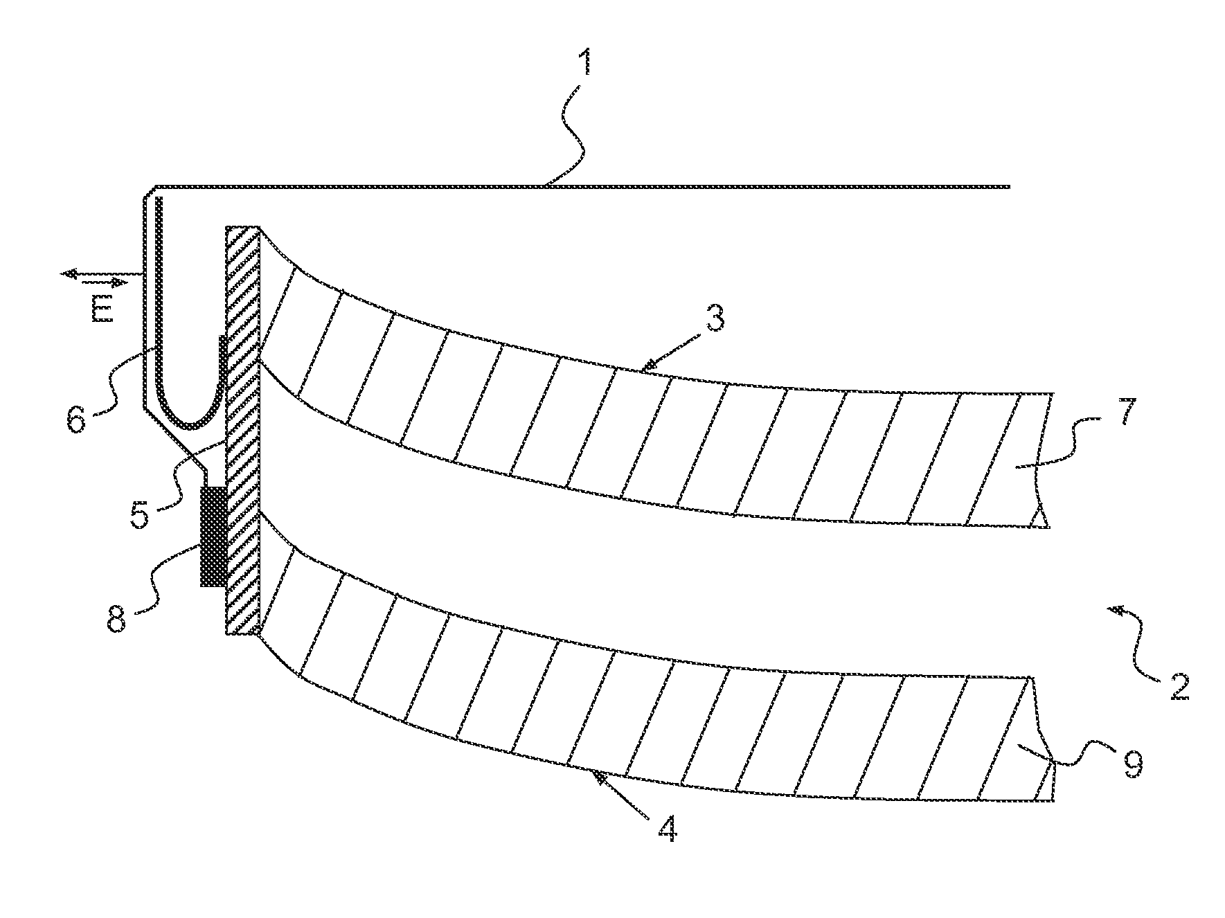
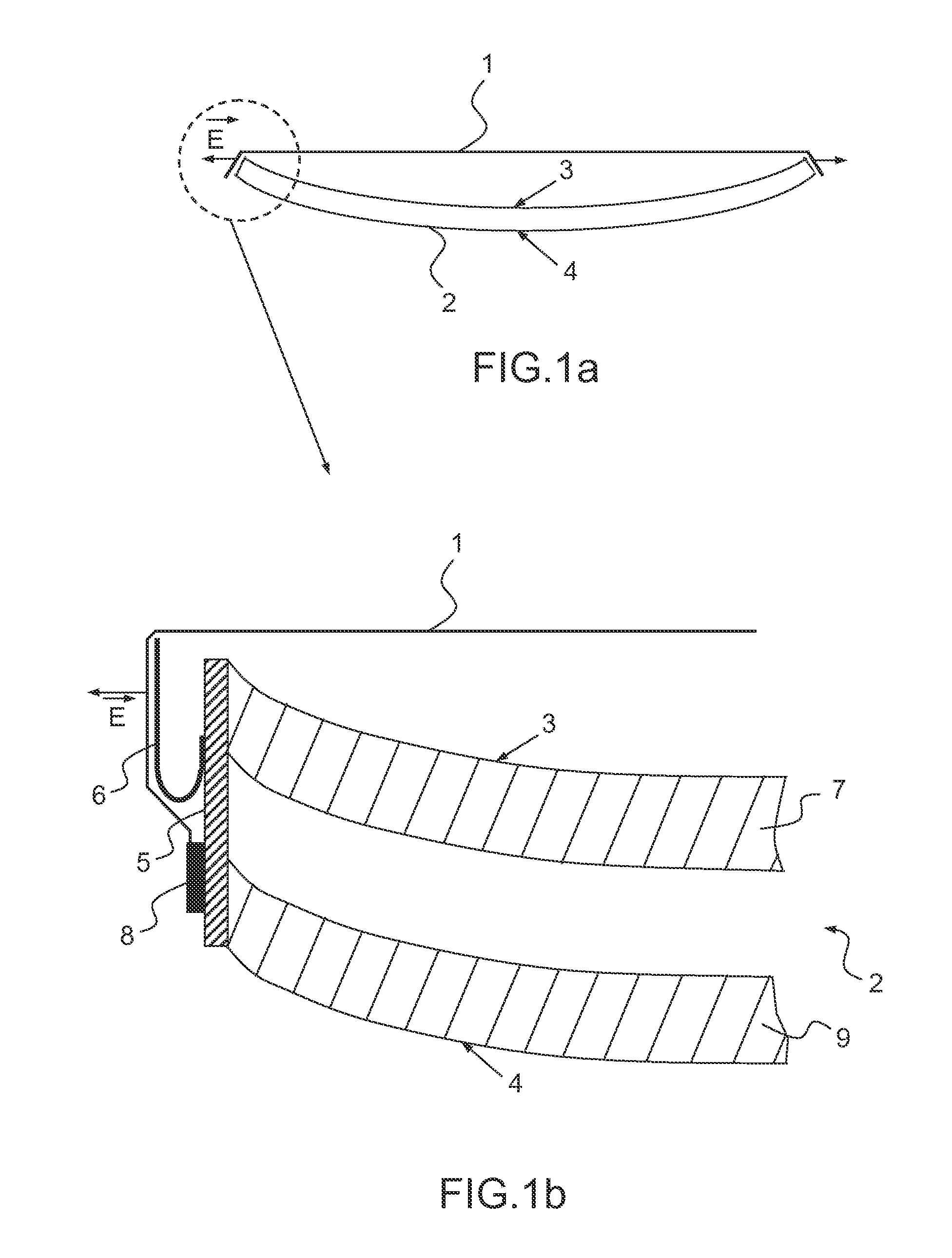
When the membrane sticks to the concave face of the reflector, the Germanium focuses the solar rays, which has the effect of damaging the elements that are in the path of a ray reflected by the concave reflecting surface of the reflector such as, for example, a radiofrequency source or else a secondary reflector.
This solution does not guarantee a permanent tension of the membrane because the antenna is subjected to temperature variations.
Moreover, at high frequency (Ka band), the Kapton® is not totally transparent to the radio waves.
However, this solution involves a prolonged immobilization of the reflector when the tensioners are installed before the membrane is attached thereto.
Moreover, the operation of attaching the membrane to the reflector is complex and difficult to reproduce.
Furthermore, this solution can be installed only on dual-grid reflectors; it cannot be installed on single reflectors or on radiating panels because the edge of these items of equipment separating the active surface from the inactive surface does not provide a smooth surface for the bonding.
Furthermore, this solution is bulky and fragile.
The tensioners that are folded in a U-shape occupy a considerable space on the periphery of the reflector and the merest impact can unstick them or break them.

Method used


Image

  • Radio Wave Transmitting Device, Antenna and Spacecraft
  • Radio Wave Transmitting Device, Antenna and Spacecraft
  • Radio Wave Transmitting Device, Antenna and Spacecraft

Examples


Embodiment Construction

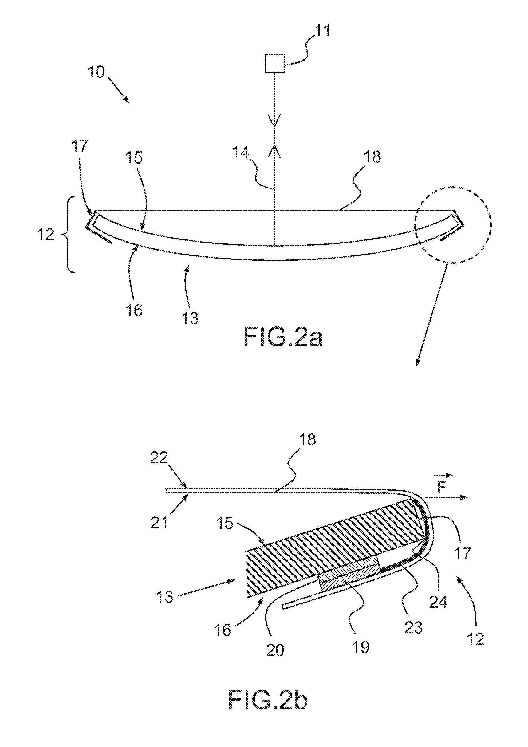
[0047]FIGS. 2a and 2b show a section of a telecommunications antenna 10 according to the invention comprising a source 11 positioned at the focus point of a device 12 for transmitting radio waves according to the invention. This device 12 comprises a reflector 13 on which radio waves are intended to be reflected from the source.

[0048]As a variant, the source may be replaced by a receiver. The waves are then reflected to the receiver.

[0049]The telecommunications antenna may be designed for space or earth applications.

[0050]The reflector 13 comprises a first active face 15 and a second inactive face 16. These faces are, in the embodiment of FIG. 2a, substantially parallel. The first face 15 and the second face 16 are joined together via an edge 17 extending continuously on the periphery of the two faces 15, 16. A membrane separates the first face 15 from space.

[0051]In the embodiments of the figures, the reflector is parabolic. The first active face 15 is concave. In the embodiment of...


PUM

PropertyMeasurementUnit
stiffnessaaaaaaaaaa
stiffnessaaaaaaaaaa
thicknessaaaaaaaaaa

Abstract

A device for transmitting radio waves comprises an item of transmitting equipment for a telecommunications antenna, a membrane for thermally protecting the reflector, and means for attaching the thermal protection membrane to the item of equipment. The thermal protection membrane is furnished with a plurality of elastic tensioners designed to keep the thermal protection membrane stretched between a first active face of the item of transmitting equipment and space, irrespective of the thermal expansions of the membrane. The item of transmitting equipment occurs in a predetermined temperature range when the attachment means attach the membrane to the item of transmitting equipment.

Description

CROSS-REFERENCE TO RELATED APPLICATION[0001]This application claims priority to foreign French patent application No. FR 1004272, filed on Oct. 29, 2010, the disclosure of which is incorporated by reference in its entirety.FIELD OF THE INVENTION[0002]The field of the invention is that of telecommunications antennas designed to transmit radio waves. These antennas are used on earth or in space or they are on board telecommunications satellites. Radio radiation is conventionally transmitted by a source coupled to one or more reflectors or else only by a radiating panel transmitting the radio radiation directly into space.BACKGROUND[0003]An attempt is usually made to minimize the thermoelastic deformations of the reflector or of the radiating panel in order to ensure stability of the directivity of the antenna. The thermoelastic deformations of the reflector or of the radiating panel originate from the cyclical thermal variations caused by passing in alternation through zones of shadow...

Claims


Application Information

Patent Timeline
Patent Type & Authority Applications(United States)
IPC IPC(8): H01Q15/14H01P11/00H01Q19/10
CPCH01Q1/288Y10T29/49016H01Q1/427
Inventor BOUGUEREAU, JEAN-LUCCALMETTES-CARENSAC, FABIEN
Owner THALES SA
Learn More