
Plastic Ball Valve Assembly

a ball valve and assembly technology, applied in the field of tools, can solve the problems of pipeline blockage and difficult opening, prior art ball valves cannot meet the connection requirements of different materials, and the pipeline is difficult to open, so as to avoid lead problems, easy to be installed, and reliable sealing

Inactive Publication Date: 2012-11-01
LINK TECH TIANJIN METAL PROD
View PDF9 Cites 16 Cited by
  • Summary
  • Abstract
  • Description
  • Claims
  • Application Information

AI Technical Summary

Benefits of technology

[0007]An object of the present invention is to provide a plastic ball valve assembly which has overcome the problems existed in prior art ball valves, meanwhile, the plastic ball valve assembly is simple in structure, convenient to discharge residual liquid in the ball, and strong in practicability.
[0018]Therefore, the advantages and the benefit effects of the present invention are described as follows. Firstly, the valve body is made of plastic material, so as so avoid lead problem when using metal ball valves. Secondly, the connecting head of the plastic ball valve assembly is capable of connecting various tubes, so as to meet the connection requirements of the pipelines with different materials. Thirdly, due to the effect of the drainage hole, when the plastic ball valve assembly is closed, the residual liquid in the ball member is discharged through the drainage hole into the outlet pipe, so as to solve the problem that frozen residual liquid leads to blockage and being hard to open the plastic ball valve assembly. Also, the plastic ball valve assembly provided by the present invention is easy to be installed, reliable to be sealed, and strong in practicability.

Problems solved by technology

However, for the rising price of copper and for the problem that using brass ball valve may cause lead in water pipeline and which is adverse to human health, people began to look for new materials to replace cooper to manufacture ball valve.
In addition, result from its structural limitation of the ball valve, one kind of ball valve body can only connect to one kind of tubes.
Therefore, the prior art ball valves will increase production costs, and under the restrictions of the raw material and production method, the prior art ball valves can not meet the connection requirements of the pipelines with different materials.
Furthermore, in colder regions or seasons, the ball valve is easy to be frozen after it is closed, which leads to pipeline blockage and being difficult to open.

Method used


Image

  • Plastic Ball Valve Assembly
  • Plastic Ball Valve Assembly
  • Plastic Ball Valve Assembly

Examples


first embodiment

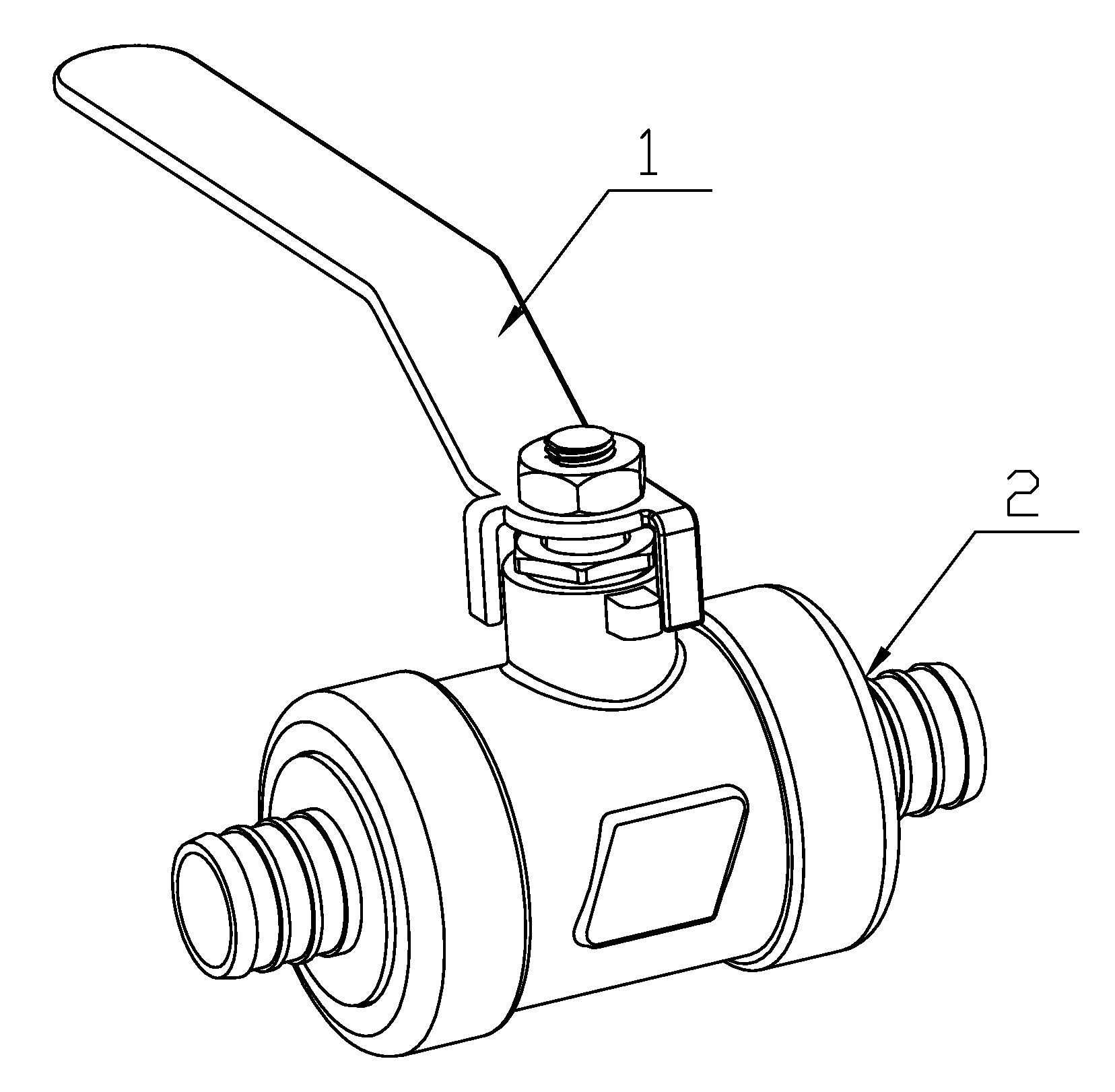
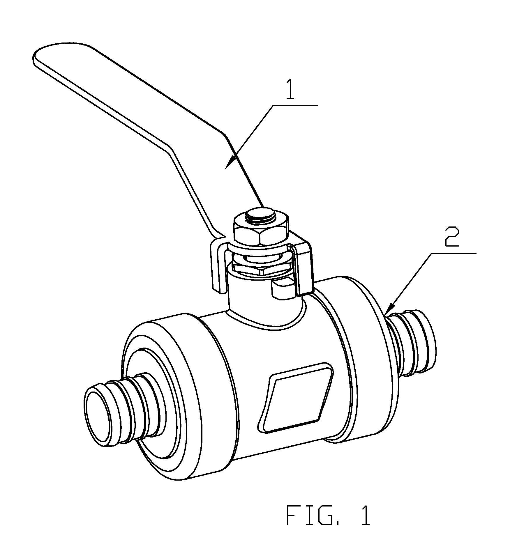
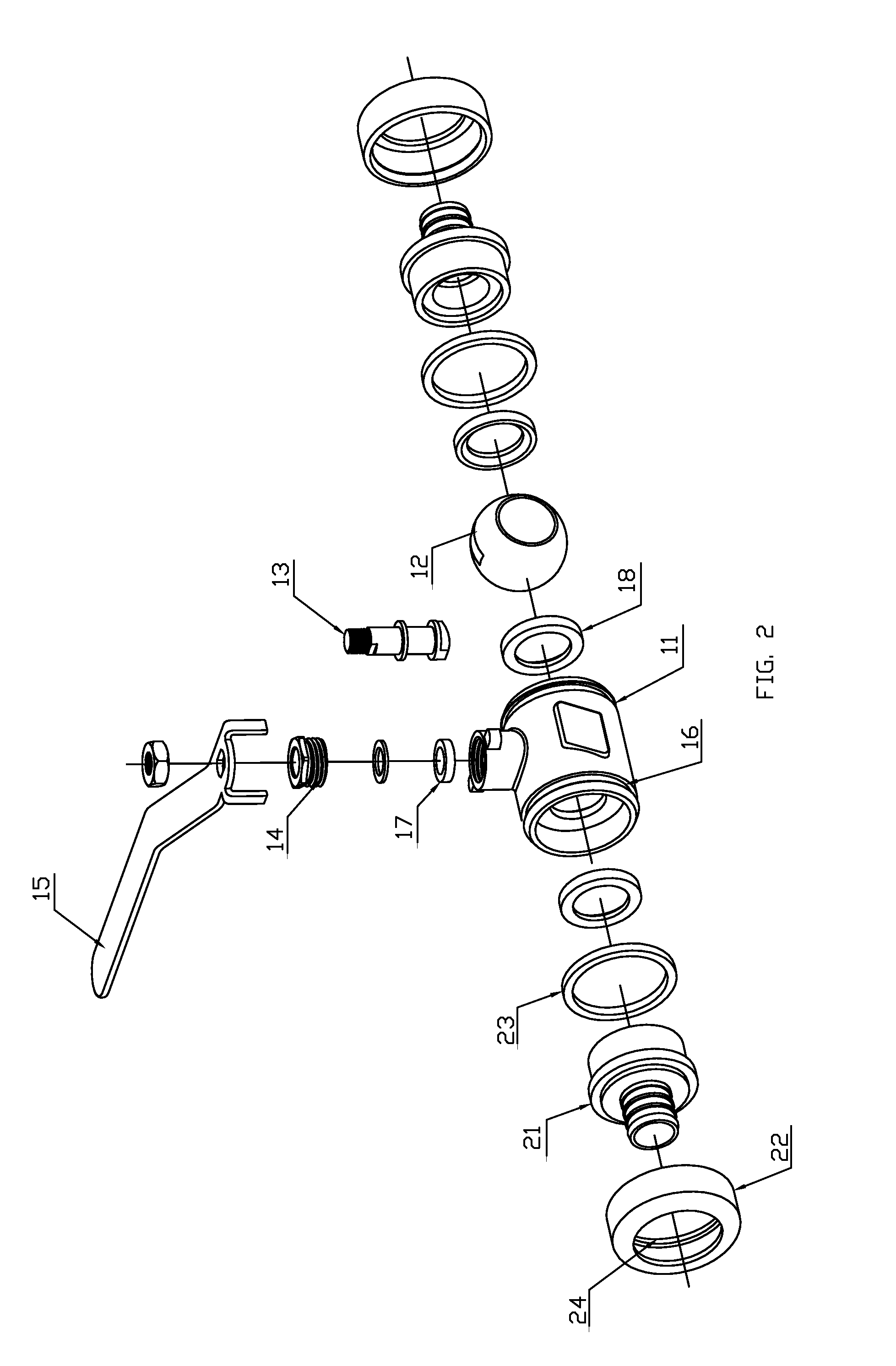
[0033]Referring to FIG. 1 to FIG. 3, FIG. 9 of the drawings, a plastic ball valve assembly comprises a valve body part 1 and a connecting part 2 adapted for detachably connecting to the valve body part 1. The valve body part 1 comprises a valve body 11 having a flow channel passing through the inside of the valve body 11, a ball member 12 has a through passage therein, a valve stem 13, a threaded pressure ring 14, a first seal ring 17, two gaskets 18, and a handle member 15. The valve body 11 has two ends, and each end has at least two recesses 16 formed on the outer surface thereof. The valve body 11 is made of plastic material.

[0034]The ball member 12 is rotatably located in the flow channel of the valve body 11 between an open condition which permits fluid flow through the flow channel and a closed condition which prevents fluid flow through the flow channel. When the plastic ball valve assembly is open, the ball member 12 at the open position, the through passage of the ball mem...

second embodiment

[0042]Referring to FIG. 4 to FIG. 6, FIG. 9 of the drawings, a plastic ball valve assembly comprises a valve body part 1 and a connecting part 2 adapted for detachably connecting to the valve body part 1. The valve body part 1 comprises a valve body 11 having a flow channel passing through the inside of the valve body 11, a ball member 12 has a through passage therein, a valve stem 13, a threaded pressure ring 14, a first seal ring 17, two gaskets 18, and a handle member 15. The valve body 11 has two ends, and each end has at least two recesses 16 formed on the outer surface thereof. The valve body 11 is made of plastic material.

[0043]The connecting part 2 comprises a pair of connecting heads 21, a pair of connecting caps 22 each having inner threads 26 formed on the inner surface of the connecting cap 22, a pair of connecting rings 28 and a pair of second seal rings 23, wherein each connecting ring 28 has two notches 25 aligned with each other on opposite sides of one end surface o...

third embodiment

[0046]Referring to FIG. 7 to FIG. 9 of the drawings, a plastic ball valve assembly comprises a valve body part 1 and a connecting part 2 adapted for detachably connecting to the valve body part 1. The valve body part 1 comprises a valve body 11 having a flow channel passing through the inside of the valve body 11, a ball member 12 has a through passage therein, a valve stem 13, a threaded pressure ring 14, a first seal ring 17, two gaskets 18, and a handle member 15. The valve body 11 has two ends, and each end has at least two recesses 16 formed on the outer surface thereof. The valve body 11 is made of plastic material.

[0047]The connecting part 2 comprises a pair of connecting heads 21, a pair of connecting caps 22, a pair of connecting rings 28 and a pair of second seal rings 23. According to the third embodiment, each connecting cap 22 has at least two projection 24 matching with the recess 16 and provided on the inner surface of one end of the connecting cap 22 for being engage...


PUM


Abstract

A plastic ball valve assembly, includes a valve body part including a valve body made of plastic material and having a flow channel passing, a ball member having a through passage therein and rotatably located in the flow channel and a handle member, and a connecting part detachably connecting with the valve body part, including a pair of connecting caps engaged with the two ends of the valve body respectively, a pair of connecting heads made of different materials, each having a head made in different shapes. The multi-use ball is easy to be installed, reliable to be sealed, and strong in practicability.

Description

BACKGROUND OF THE PRESENT INVENTION[0001]1. Field of Invention[0002]The present invention relates to tools used in pipeline connection, and more particularly to a plastic ball valve assembly.[0003]2. Description of Related Arts[0004]At present, pipelines have been widely applied in industry, agriculture and urban construction, such as used in water supply and gas supply, etc. A ball valve in the pipeline is mainly used to cut off or distribute a media flow, or to change the direction of a media flow. Due to its compact structure, reliable sealing, easy operation and maintenance, the ball valve is comprehensively applied in various filed. In recent years, most of the ball valves which are have been widely used are metal ball valves (such as brass ball valve, stainless steel ball valve, etc.). However, for the rising price of copper and for the problem that using brass ball valve may cause lead in water pipeline and which is adverse to human health, people began to look for new materi...

Claims


Application Information

Patent Timeline
Patent Type & Authority Applications(United States)
IPC IPC(8): F16K5/06
CPCF16K5/0642F16K27/067F16K5/0657
Inventor ZHANG, LEI
Owner LINK TECH TIANJIN METAL PROD
Learn More