
System and method for simultaneous MIMO signal testing with single vector signal analyzer

a technology of simultaneous mimo signal and analyzer, which is applied in the field of systems and methods for testing mimo signal systems, can solve the problems of increasing the cost of such testers with the increase of simultaneous signals, and the inability to decode the resultant composite signals

Inactive Publication Date: 2012-10-25
LITEPOINT
View PDF7 Cites 23 Cited by
  • Summary
  • Abstract
  • Description
  • Claims
  • Application Information

AI Technical Summary

Problems solved by technology

Ordinarily, doing so would cause the signals to interfere with each other making it impossible to decode the resulting composite signals.
The cost of such testers would therefore increase with the increased number of simultaneous signals to be measured.

Method used


Image

  • System and method for simultaneous MIMO signal testing with single vector signal analyzer
  • System and method for simultaneous MIMO signal testing with single vector signal analyzer
  • System and method for simultaneous MIMO signal testing with single vector signal analyzer

Examples


Embodiment Construction

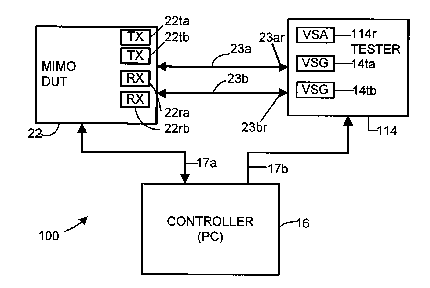
[0032]The following detailed description is of example embodiments of the presently claimed invention with references to the accompanying drawings. Such description is intended to be illustrative and not limiting with respect to the scope of the present invention. Such embodiments are described in sufficient detail to enable one of ordinary skill in the art to practice the subject invention, and it will be understood that other embodiments may be practiced with some variations without departing from the spirit or scope of the subject invention.

[0033]Throughout the present disclosure, absent a clear indication to the contrary from the context, it will be understood that individual circuit elements as described may be singular or plural in number. For example, the terms “circuit” and “circuitry” may include either a single component or a plurality of components which are either active and / or passive and are connected or otherwise coupled together (e.g., as one or more integrated circu...


PUM


Abstract

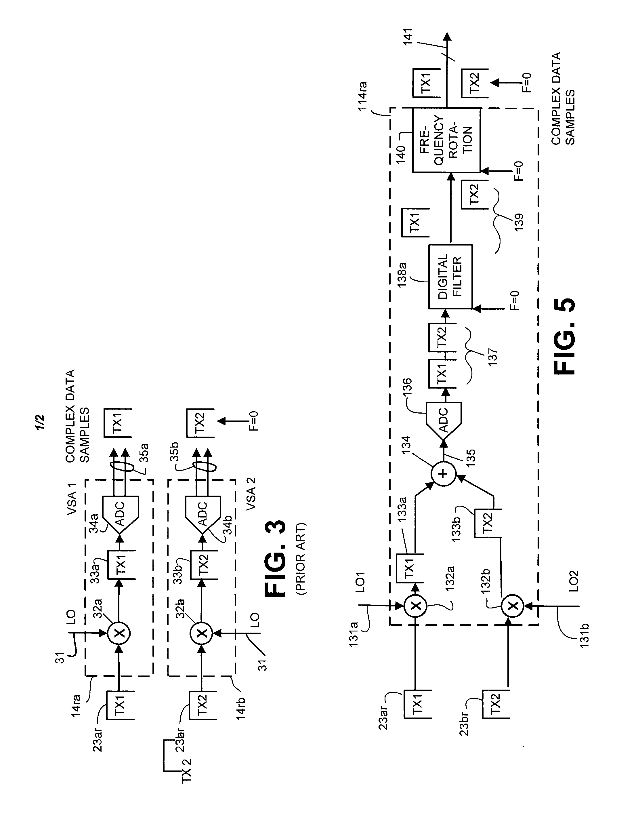
Signal conversion circuitry and method for converting a multiple input, multiple output (MIMO) packet data signal transmission to a plurality of complex data samples for processing by shared test equipment, e.g., a single vector signal analyzer (VSA).

Description

BACKGROUND OF THE INVENTION[0001]1. Field of the Invention[0002]The present invention relates to systems and methods for testing MIMO signal systems, and in particular, testing such systems using minimal test equipment.[0003]2. Related Art[0004]Many modern devices utilize wireless signals to send and receive data. Handheld devices in particular make use of wireless connections to provide features including telephony, digital data transfer, and geographical positioning. Although a variety of different wireless-connectivity capabilities are used (such as WiFi, WiMAX, and Bluetooth), in general each is defined by an industry-approved standard (such as IEEE 802.11, IEEE 802.16 and IEEE 802.15, respectively). In order to communicate using these wireless-connectivity capabilities, devices must adhere to the parameters and limitations specified by the associated standards.[0005]Although differences exist between wireless communication specifications (for example, in the frequency spectra, ...

Claims


Application Information

Patent Timeline
Patent Type & Authority Applications(United States)
IPC IPC(8): H04L27/00H04B1/02
CPCH04B7/0413H04L1/24H04B17/00H04L27/26
Inventor OLGAARD, CHRISTIAN VOLFWANG, RUIZU
Owner LITEPOINT
Learn More