
Color filter substrate and display device

Inactive Publication Date: 2012-10-25
E INK HLDG INC
View PDF3 Cites 10 Cited by
  • Summary
  • Abstract
  • Description
  • Claims
  • Application Information

AI Technical Summary

Benefits of technology

[0007]The present invention is to provide a color filter substrate, which has a high light reflectivity, and facilitates

Problems solved by technology

The display brightness is accordingly influenced by the decrease of the total light

Method used


Image

  • Color filter substrate and display device
  • Color filter substrate and display device
  • Color filter substrate and display device

Examples


Embodiment Construction

[0028]It is to be understood that other embodiment may be utilized and structural changes may be made without departing from the scope of the present invention. Also, it is to be understood that the phraseology and terminology used herein are for the purpose of description and should not be regarded as limiting. The use of “including,”“comprising,” or “having” and variations thereof herein is meant to encompass the items listed thereafter and equivalents thereof as well as additional items. Unless limited otherwise, the terms “connected,”“coupled,” and “mounted,” and variations thereof herein are used broadly and encompass direct and indirect connections, couplings, and mountings.

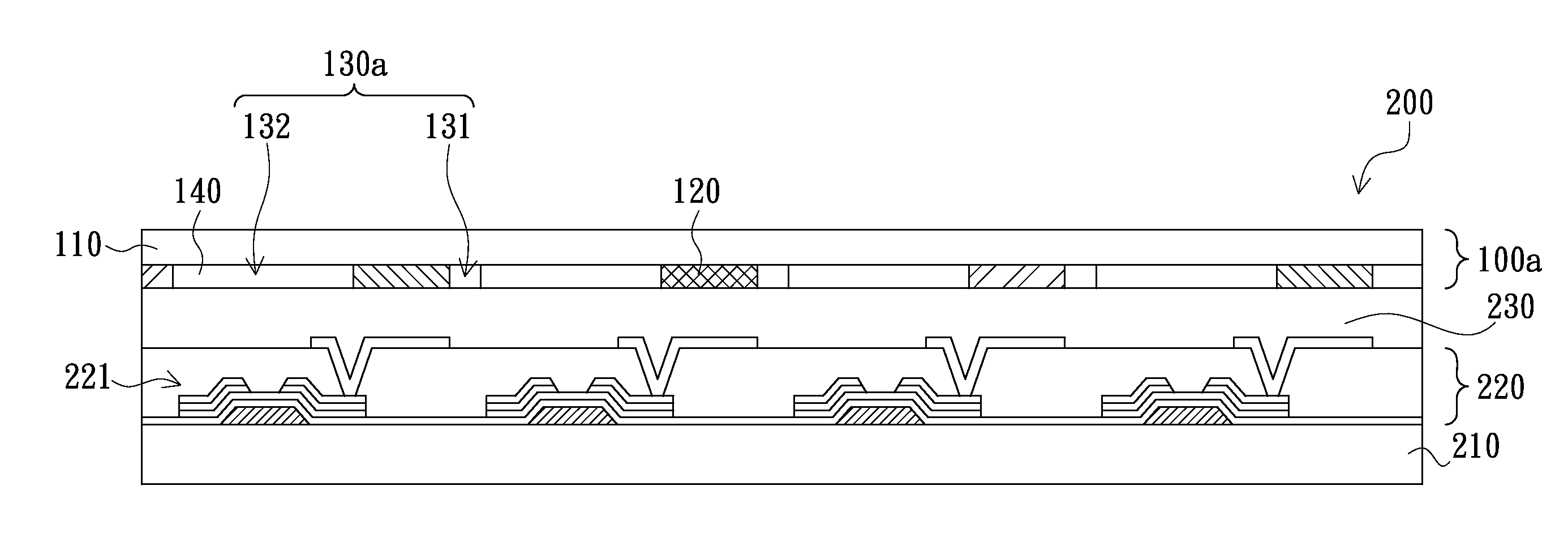
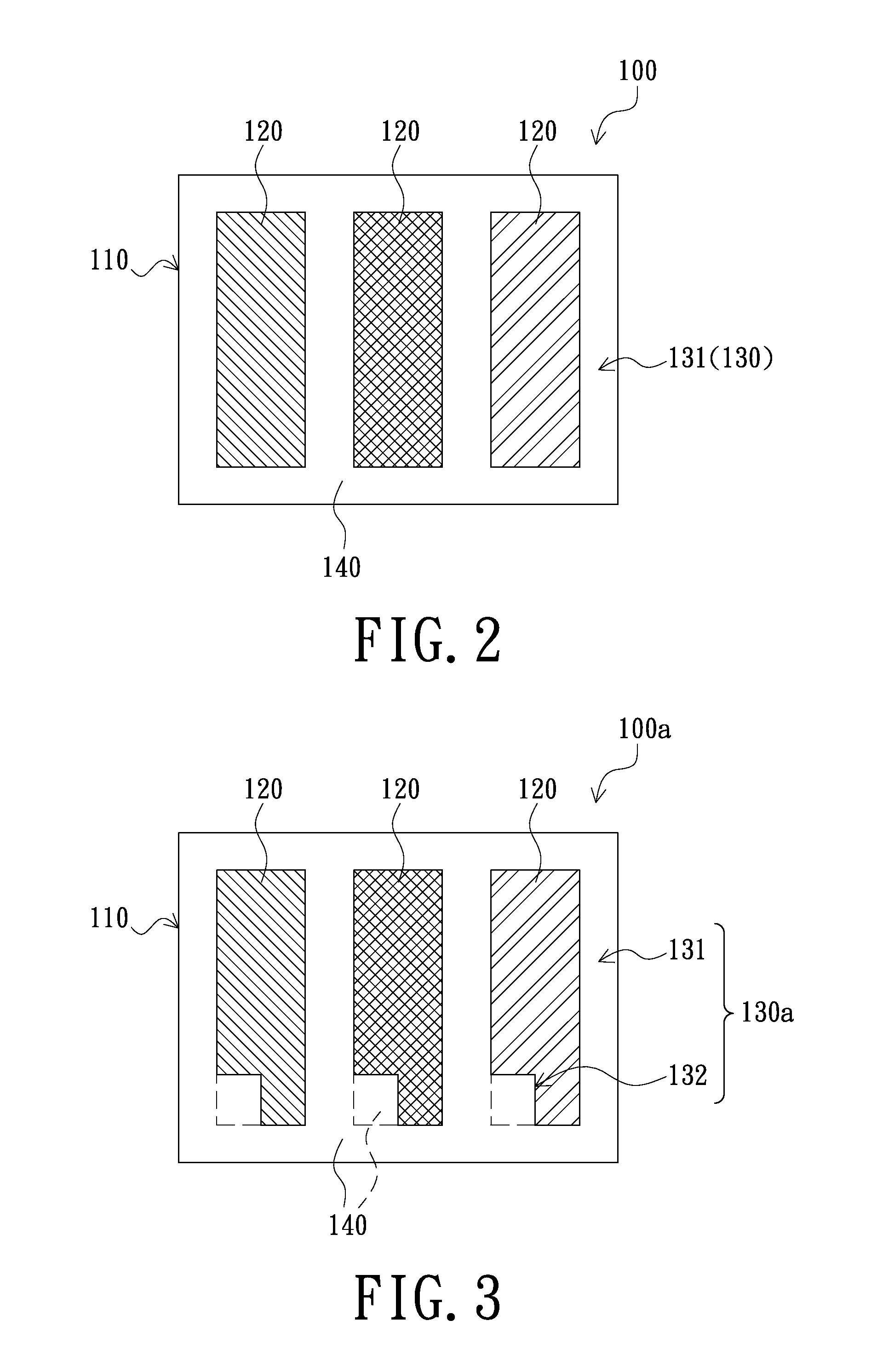
[0029]A color filter substrate includes a plurality of pixels. Because the pixels have similar structures, in the following drawings, the color filter substrate is represented by one of the pixels of the color filter substrate.

[0030]FIG. 2 is a schematic, top view of a color filter substrate according to a ...


PUM


Abstract

A color filter substrate includes a transparent substrate, a number of color photoresists disposed on the transparent substrate and a high-reflecting region disposed on the transparent substrate. The high-reflecting region at least includes a first region for separating the color photoresists. The high-reflecting region either is filled with a reflecting material or is empty. A display device is also provided. The display device includes a lower substrate, a driving circuit layer disposed on the lower substrate, a display layer disposed on the driving circuit layer and the above-mentioned color filter substrate disposed on the display layer. The color filter substrate can be assembled to the display device to increase the total light intensity of light reflection, thereby improving the display quality of the display device.

Description

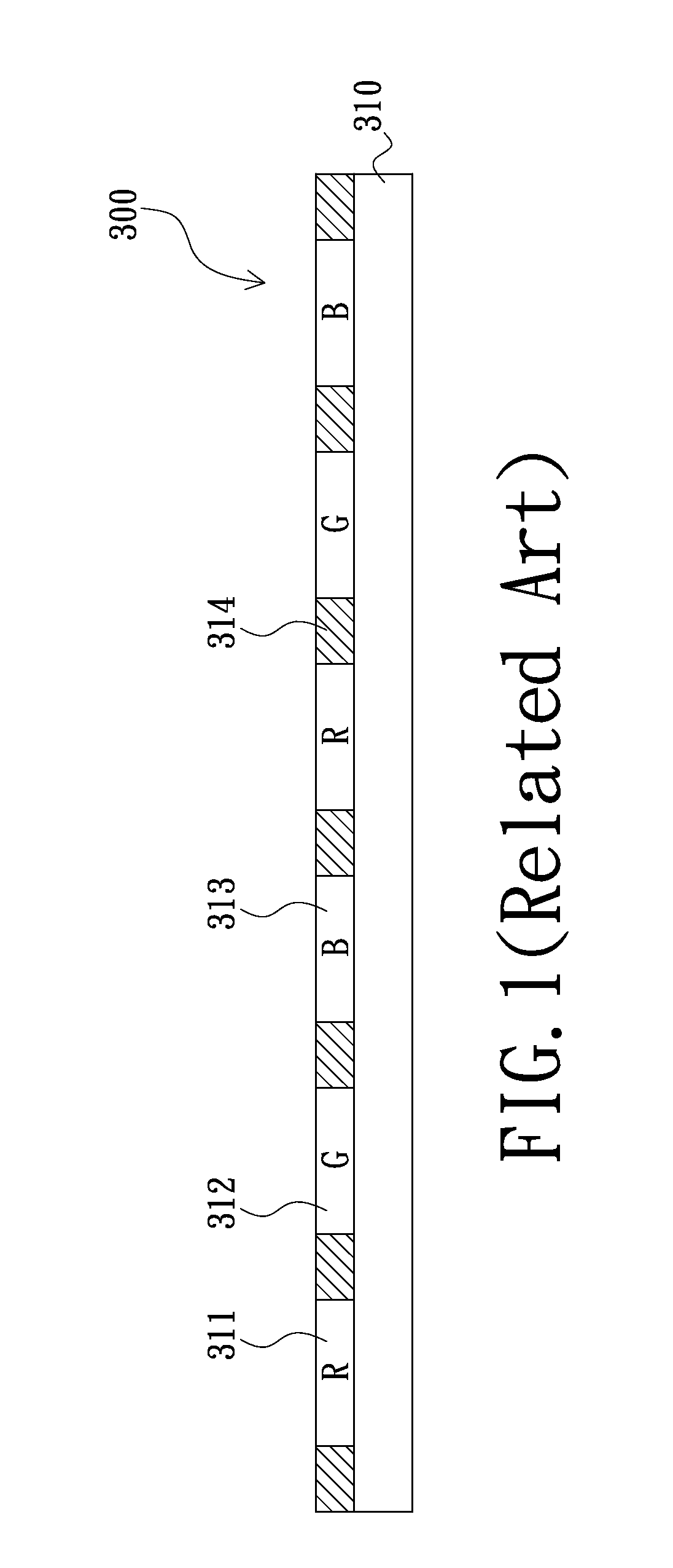
BACKGROUND[0001]1. Technical Field[0002]The present invention relates to a display device, more particularly to a color filter substrate and a display device applied such color filter substrate.[0003]2. Description of the Related Art[0004]Traditional electrophoretic display devices are black and white display devices. In order to make the electrophoretic display devices stand more competitive power, the color filter substrates are generally used to achieve a colorful effect of the traditional electrophoretic display devices. Thus, the electrophoretic display devices can satisfy the colorful trend of the current display devices.[0005]FIG. 1 is a schematic, cross-sectional view of a traditional color filter substrate. Referring to FIG. 1, a traditional color filter substrate 300 includes a number of red photoresists 311, a number of green photoresists 312 and a number of blue photoresists 313 disposed on a transparent substrate 310. The red photoresists 311, the green photoresists 312...

Claims


Application Information

Patent Timeline
IPC IPC(8): G02F1/1335G02F1/167G02F1/1677
CPCG02F1/167G02F1/133514G02F1/1677
Inventor WANG, YI-CHINGTSAN, SHEN-CHI
Owner E INK HLDG INC
Learn More