
Subsea sampling system and method

a sampling system and subsea technology, applied in the field of subsea sampling systems, can solve the problems of difficult and/or inefficient sampling of samples for further analysis, problematic deposition of such materials, etc., and achieve the effect of enhancing the ability to adjust the system and being more protected from damage and clogging

Inactive Publication Date: 2012-10-25
SCHLUMBERGER TECH CORP
View PDF13 Cites 25 Cited by
  • Summary
  • Abstract
  • Description
  • Claims
  • Application Information

AI Technical Summary

Benefits of technology

[0016]The system may further include a plurality of fluid pumps which may be used for returning the fluid sample back into the fluid flowline, pressure testing the ROV connection, tuning a flow conditioner, maintaining line conditions within the fluid sample collector, unblocking or cleaning the sampling probe, the fluid connector or flowline, and / or deploying the sampling probe. Furthermore, the ROV may include a full bore pipeline bypass for simplifying the intervention of the sampling probe.
[0036]One of the advantages provided by the current system and method for monitoring and analysis of fluids in a flowline is that it allows the use of systems and methods for sampling and analysis of fluids to be implemented in the subsea environment while keeping the sample fluid at line conditions. A further advantage is that the sample probe is removable from the flowline and may therefore be more protected from damage and clogging. Another advantage is the representivity of the sampling process, i.e. the sample phases can be selected and adequate quantities from these sample phases can be captured through an enrichment process. Another advantage is the capability of “no-sample-to-surface” concept wherein a fluid sample may be collected, analyzed on the ROV skid, and discarded back into one of the flowlines. An exemplary system and method of the present disclosure also allows for convenient cleaning and unblocking of the sample probe and sample fluid conduits.
[0037]Even further, the system and method can be adjusted subsea and thus used for a very wide range of fluids encountered subsea, from lean gas to heavy oil. The ability for the system to be adjusted is enhanced by the use of selected sensors which are deployed with the system, and which allow for the selective sampling of fluids of interest.
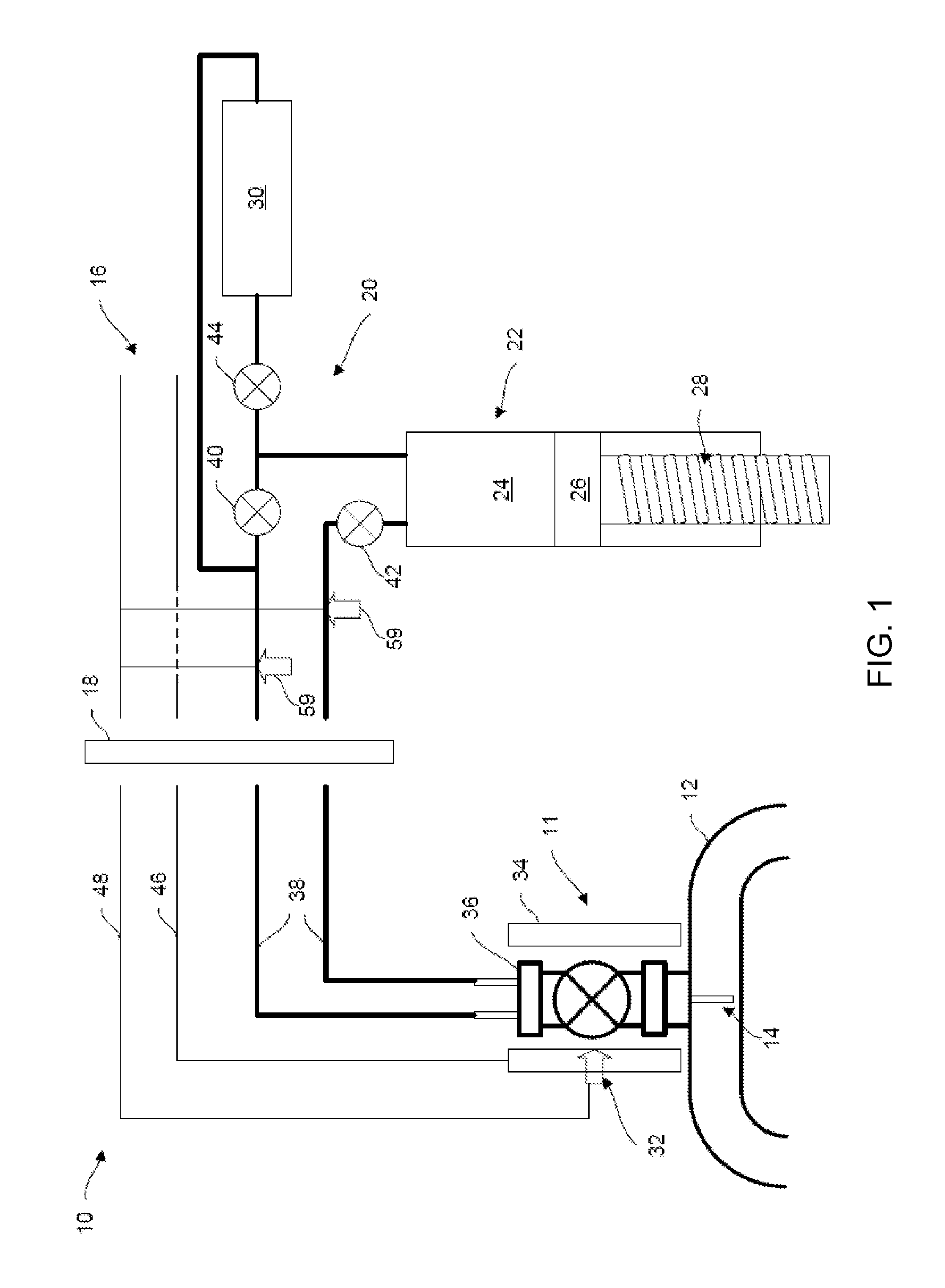
[0039]The system and method of the present disclosure include a subsea sampling device preferably permanently or semi-permanently attached to the flowline or wellhead for capturing a multiphase sample from the flowline or wellhead. In one embodiment, subsea sampling device is as a commercially available device called subsea sampler and offered by Framo Engineering. The system further includes a remotely operated vehicle (ROV) sampling skid assembly and a device for docking the ROV to the permanently installed sampling device and making all electrical, fluid and communication connections as necessary. The ROV sampling skid is equipped with an enrichment system for separating oil, water or gas samples from the multiphase sample, as well as a device for storing the separated samples in pressurized bottles. Upon docking of the ROV skid to the permanently installed sampling device, the sampling sequence is initiated to transfer a sample taken from the permanently installed subsea sampling device to the ROV skid sample enrichment process. Monophasic samples are then collected and stored in the pressurized bottles on the ROV skid. The ROV skid can then transfer the samples to a surface facility. The system further includes a device for ensuring that the samples that are taken are representative (e.g., in terms of composition) of the phases flowing at flowline or well head conditions (e.g., in terms of pressure and temperature). The system allows the taking of sufficient quantities of monophasic samples to enable further fluid analysis, as needed.

Problems solved by technology

In subsea applications, problematic deposition of such materials can occur as a result of the temperature and pressure gradients between a subsea wellhead and the surface.
However, the detection of the various well parameters and the taking of samples for further analysis can be difficult and / or inefficient, particularly in certain environments, such as subsea environments.

Method used


Image

  • Subsea sampling system and method
  • Subsea sampling system and method
  • Subsea sampling system and method

Examples


Embodiment Construction

[0053]Specific embodiments of the present disclosure will now be described in detail with reference to the accompanying drawings. Further, in the following detailed description of embodiments of the present disclosure, numerous specific details are set forth in order to provide a more thorough understanding of the disclosure. However, it will be apparent to one of ordinary skill in the art that the embodiments disclosed herein may be practiced without these specific details. In other instances, well-known features have not been described in detail to avoid unnecessarily complicating the description.

[0054]The terminology and phraseology used herein is solely used for descriptive purposes and should not be construed as limiting in scope. Language such as “including,”“comprising,”“having,”“containing,”“consisting of,” or “involving,” and variations thereof, is intended to be broad and encompass the subject matter listed thereafter, equivalents, and additional subject matter not recited...


PUM


Abstract

A system and method are provided for collecting fluid samples from a fluid flowline located subsea. The system includes a multiphase sampling apparatus attachable to the flowline, and a vehicle sampling apparatus that is connectable to the multiphase sampling apparatus to allow the transfer of the collected fluid sample thereto. The vehicle sampling apparatus is preferably a subsea remotely operated vehicle (ROV) locatable proximate the fluid flowline and having a fluid sample collector and a fluid pump for transferring the collected fluid sample from the multiphase sampling apparatus to the fluid sample collector. The vehicle sampling apparatus includes a fluid analysis sensor capable of extracting information about the collected fluid sample at a subsea location. Optionally, the vehicle sampling apparatus can transport the collected fluid sample to a location remote from the fluid flowline for analysis.

Description

CROSS REFERENCE TO RELATED APPLICATIONS[0001]The present disclosure is based on and claims the benefit of priority from U.S. Provisional Patent Application Ser. No. 61 / 160,446 of Brown et al, entitled “SUBSEA SAMPLING SYSTEM AND METHOD,” filed on Mar. 16, 2009; U.S. Provisional Patent Application Ser. No. 61 / 166,998 of Brown et al, entitled “SUBSEA SAMPLING SYSTEM AND METHOD,” filed on Apr. 6, 2009; U.S. Provisional Patent Application Ser. No. 61 / 232,487 of Brown et al., entitled “ISOTHERMAL SUBSEA SAMPLING SYSTEM AND METHOD,” filed on Aug. 10, 2009; and U.S. Provisional Patent Application Ser. No. 61 / 285,323 of Theron et al, entitled “SUBSEA SAMPLING SYSTEM AND METHOD,” filed on Dec. 10, 2009; the entire contents of the disclosures of which are hereby incorporated by reference.TECHNICAL FIELD[0002]The present disclosure relates generally to sampling fluids in the oil and gas industry. More particularly, the present disclosure relates to an apparatus, system and method for sampling ...

Claims


Application Information

Patent Timeline
Patent Type & Authority Applications(United States)
IPC IPC(8): E21B49/08E21B27/00
CPCE21B41/0007E21B49/08G01N1/02G01N33/28G01N2035/0489G01N1/2035E21B49/001
Inventor BROWN, JONATHAN W.BOE, ASMUNDGUIEZE, PAUL B.KERR, JOHN A.VASQUES, RICARDOTHERON, BERNARD E.
Owner SCHLUMBERGER TECH CORP
Learn More