Above-the-Knee Modular Prosthesis System

a modular prosthesis and upper-knee technology, applied in the field of prosthesis, can solve the problems of high gait dysfunction and disability, difficult to fabricate custom-fitted prosthesis, and high cost of providing conventional manufacturing methods,

Inactive Publication Date: 2012-10-11
IFIT PROSTHETICS
View PDF4 Cites 19 Cited by
  • Summary
  • Abstract
  • Description
  • Claims
  • Application Information

AI Technical Summary

Benefits of technology

[0025]The present invention is a modular prosthesis system comprised of an outer housing, connector assembly and prosthetic shank. The connector is made up of two main components: an upper plate which is secured to the outer housing and a lower plate which is secured around a pipe connector that attaches to the knee device. The design of the connector allows for angular adjustment which ensures proper positioning and alignment of the knee, shank, and foot. In addition, the housing includes a liner and tightening components, resulting in a prosthesis that may be fit to any residual limb and which can accommodate long-term and daily changes in the amputee and residual limb as well as other aspects of an amputee's dynamic stress distribution profile.

Problems solved by technology

The transfemoral (above knee) level of amputation is less common than the below knee (transtibial) level of limb loss, but results in the highest level of gait dysfunction and disability.
Further, the transfemoral level is difficult to fit with a prosthetic socket due to redundant soft tissues and variable lengths and sizes of the residual limb.
A comfortable custom-fitted prosthesis is difficult to fabricate and costly to provide using conventional manufacturing techniques.
In addition, there are additional costs to ensure the comfort and functionality of the device including replacement or revision of the socket.
However, devices such as computerized knee mechanisms and energy storing feet are costly and beyond the economic means of many prosthetic users, particularly those in nations outside the United States.
Insurance coverage of such prosthetic devices is variable across insurers and has often impeded prescription and availability of high quality devices even for amputees with insurance coverage.
The uninsured often go without comfortable prosthetic devices for long periods of time before public insurance enables them to receive a functional prosthesis.
These prosthesis systems, however, have several limitations.
They are difficult to fabricate and require specialized facilities for initial manufacturing (e.g., casting) and subsequent adjustments.
These systems all require expertise and consulting support that is not widely available.
In particular, the socket (i.e., the portion of the prosthesis into which the residual limb fits), socket attachment, and alignment aspects of the device seem to be a common problematic area of development.

Method used


Image

  • Above-the-Knee Modular Prosthesis System
  • Above-the-Knee Modular Prosthesis System
  • Above-the-Knee Modular Prosthesis System

Examples


Embodiment Construction

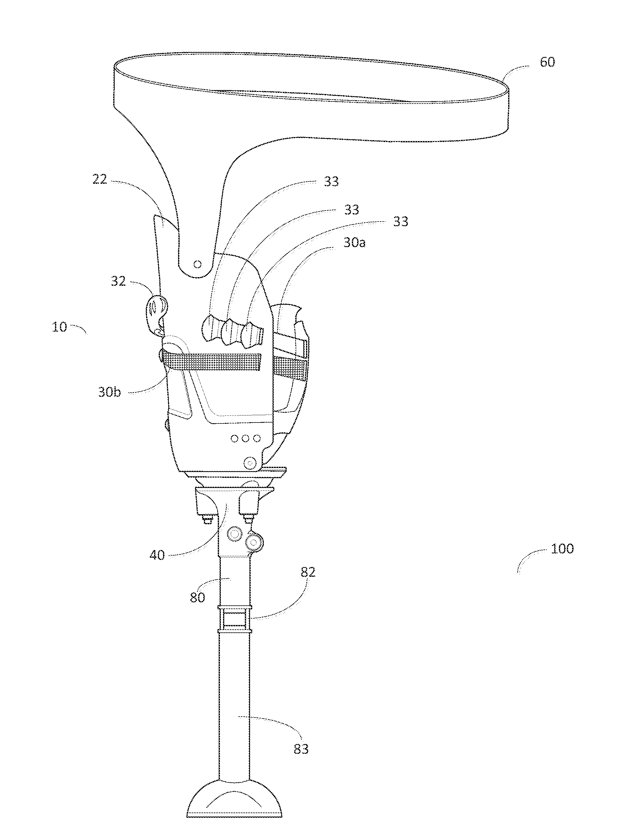
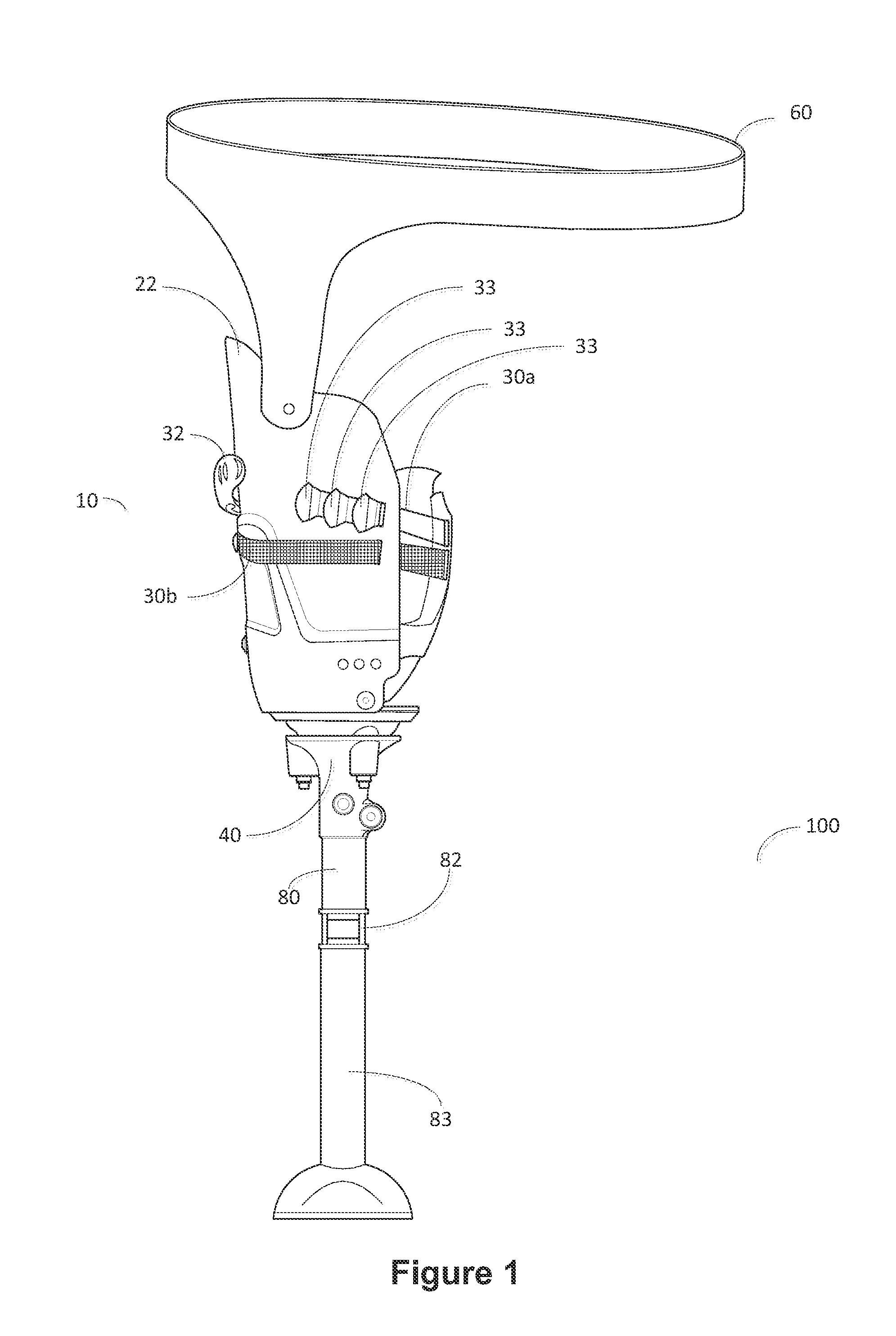
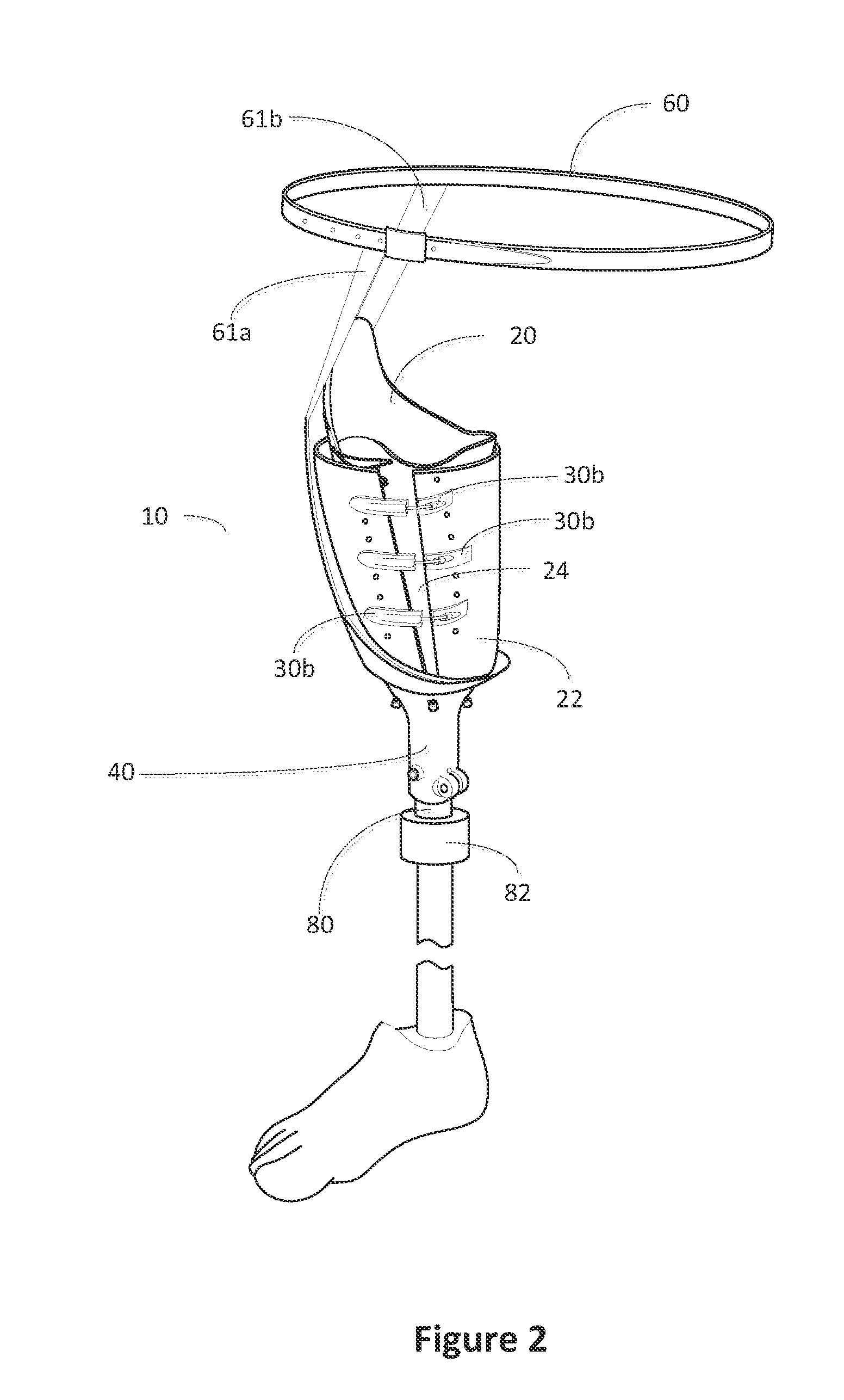
[0026]For the purpose of promoting an understanding of the present invention, references are made in the text to exemplary embodiments of a modular prosthesis system, only some of which are described herein. It should be understood that no limitations on the scope of the invention are intended by describing these exemplary embodiments. One of ordinary skill in the art will readily appreciate that alternate but functionally equivalent materials, component, and designs may be used. The inclusion of additional elements may be deemed readily apparent and obvious to one of ordinary skill in the art. Specific elements disclosed herein are not to be interpreted as limiting, but rather as a basis for the claims and as a representative basis for teaching one of ordinary skill in the art to employ the present invention.

[0027]It should be understood that the drawings are not necessarily to scale; instead, emphasis has been placed upon illustrating the principles of the invention. In addition, ...


PUM


Abstract

An above-the-knee modular prosthetic system contains an outer housing and connector assembly which may both be adjusted to create a custom-like fit for a residual limb. The outer housing contains an inner liner which provides circumference and volume adjustability, while an outer shell adjusts for circumference of a residual limb only. A plurality of additional adjustment components may provide additional customization for the volume, circumference, shape, angle and other physical properties of a residual limb. A connector assembly connects the outer housing to a knee, shank and foot known in the art. The connector assembly contains an upper plate and a lower plate which are adjustably connected to provide adjustments for the angle and position at which a residual limb is connected to a prosthetic limb.

Description

CROSS-REFERENCE TO RELATED APPLICATION[0001]This application is a continuation-in-part of U.S. patent application Ser. No. 13 / 083,403 entitled “Modular Prosthesis System,” filed on Apr. 8, 2011, and U.S. patent application Ser. No. 13 / 274,130 entitled “Rapid Fit Modular Prosthetic Device for Accommodating Gait Alignment and Residual Limb Shape and Volume,” filed on Oct. 14, 2011, which are hereby incorporated by reference in their entirety.FIELD OF INVENTION[0002]The present invention relates to the field of prostheses, and more particularly to a modular prosthesis system for above-the-knee amputees.BRIEF DESCRIPTION OF THE DRAWINGS[0003]FIG. 1 illustrates an exemplary embodiment of an above-the-knee modular prosthesis system.[0004]FIG. 2 illustrates an alternative embodiment of an above-the-knee modular prosthesis system with soft inner liner.[0005]FIGS. 3a and 3b illustrate exemplary connector assemblies for a modular prosthesis system.[0006]FIG. 4 is an exploded view of an exempl...

Claims


Application Information

Patent Timeline
Patent Type & Authority Applications(United States)
IPC IPC(8): A61F2/60A61F2/78
CPCA61F2/60A61F2/601A61F2/64A61F2/76A61F2/78A61F2/7812A61F2002/7881A61F2002/5018A61F2002/502A61F2002/5026A61F2002/608A61F2002/7862A61F2/80
Inventor DILLINGHAM, TIMOTHY
Owner IFIT PROSTHETICS
Why Eureka
Try Eureka