
Explosion-protected plug-in connector

a plug-in connector and explosion-protected technology, applied in the direction of electrically conductive connections, telephone connectors, electrical apparatus, etc., can solve the problems of unintentional loosening of spring terminals, complicated procedure methods in assembly technology, and the inability to completely prevent the formation of sparks, etc., to achieve compact and cost-advantage

Inactive Publication Date: 2012-10-11
FHF FUNKE HUSTER FERNSIG
View PDF14 Cites 0 Cited by
  • Summary
  • Abstract
  • Description
  • Claims
  • Application Information

AI Technical Summary

Benefits of technology

[0012]Within the scope of the invention, a specially designed explosion-protected plug-in connector is therefore used. This falls back on two IDC terminal units that are contacted with the conductor end section of the network. In this connection, the IDC terminal units are designed to be redundant. This means that in the case of failure of the one IDC terminal unit, contacting of a circuit board, an electrical device, a VoIP telephone, etc. with the network takes place by way of the other IDC terminal unit. As a result, spark formation is prevented, even in the case of a damaged electrical connection between the conductor end section and the one IDC terminal unit. This is because the electrical connection to the other IDC terminal unit continues to exist. As a result, the explosion-protected plug-in connector according to the invention is predestined for use in areas at risk of explosion.
[0020]As has already been explained, the two IDC terminal units are advantageously connected with one and the same common circuit board. In order to design the circuit board with the electrical / electronic components situated on it so as to be explosion-protected, it is preferable if the circuit board is enclosed by a casting mass. Then the design is made in such a manner that the two IDC terminal units are the only items that emerge out of the casting mass in question, which encloses the circuit board. As an alternative to the casting mass, however, it is also possible to work with a circuit board that is designed to be inherently safe. The inherent safety of the circuit board can be implemented, in terms of design—with and without recourse to casting mass—in such a manner that in case of a failure, current and / or voltage are limited so that spark formation is reliably prevented.
[0023]In the end result, an explosion-protected plug-in connector is made available, the two IDC terminal units of which are connected with the conductor end section of the network, taking true redundancy into consideration. In this manner, any electrical device to be connected with the network can be perfectly and safely contacted in the area that is at risk of explosion, using the plug-in connector according to the invention.
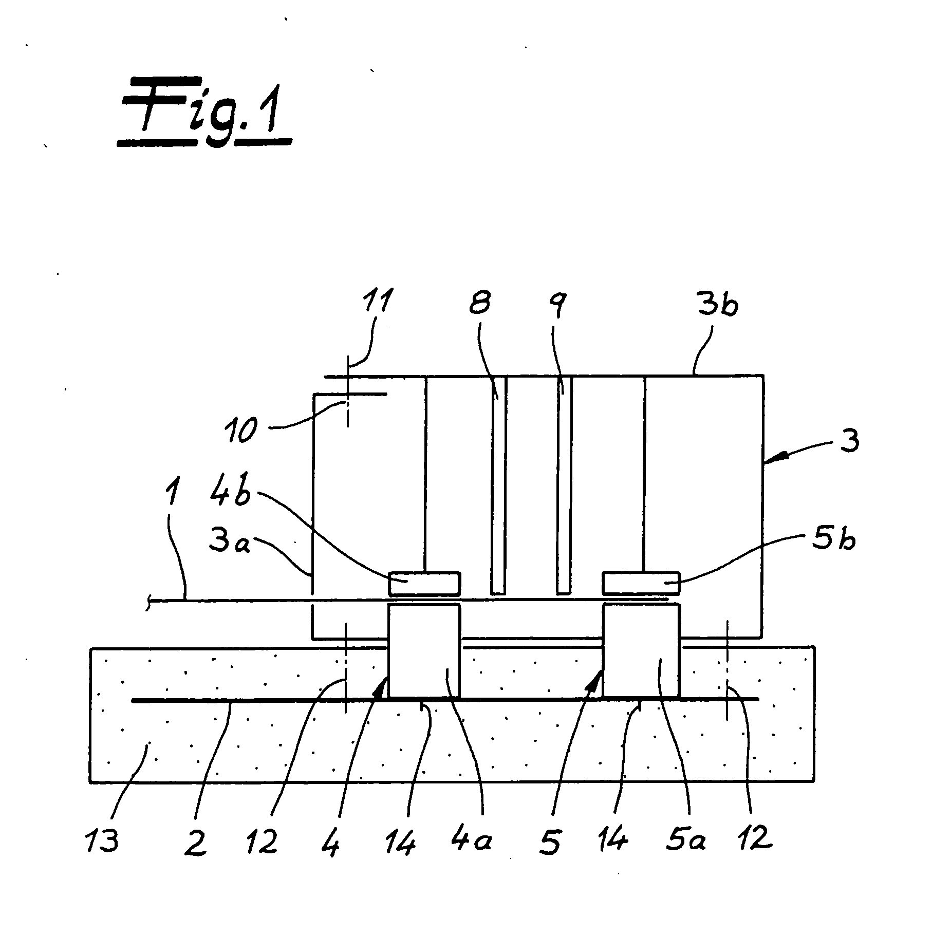
[0025]All of this is possible, taking a particularly compact and cost-advantageous structure into consideration. This is because all that is required for assembly is to lay the leads of the network cable to be connected, or its conductor end section, into the IDC terminals of the two IDC terminal units. As soon as the housing is now closed, in that the roof enters into a connection with the floor, the assembly plug parts, which are typically provided in the roof, ensure that the individual leads in the related IDC terminal plug part are perfectly contacted. At the same time, the hold-down that submerges between the two IDC terminal units during this process ensures that the conductor end section cannot come loose from the one or the two IDC terminal units. These are the significant advantages.

Problems solved by technology

Such a method of procedure is complicated in terms of assembly technology and might be problematic due to safety aspects, under some circumstances, because a lead break can occur in connection with screw terminals and improper attachment, for example.
Unintentional loosening processes in the case of spring terminals and the accompanying spark formation also cannot be entirely precluded.

Method used


Image

  • Explosion-protected plug-in connector
  • Explosion-protected plug-in connector
  • Explosion-protected plug-in connector

Examples


Embodiment Construction

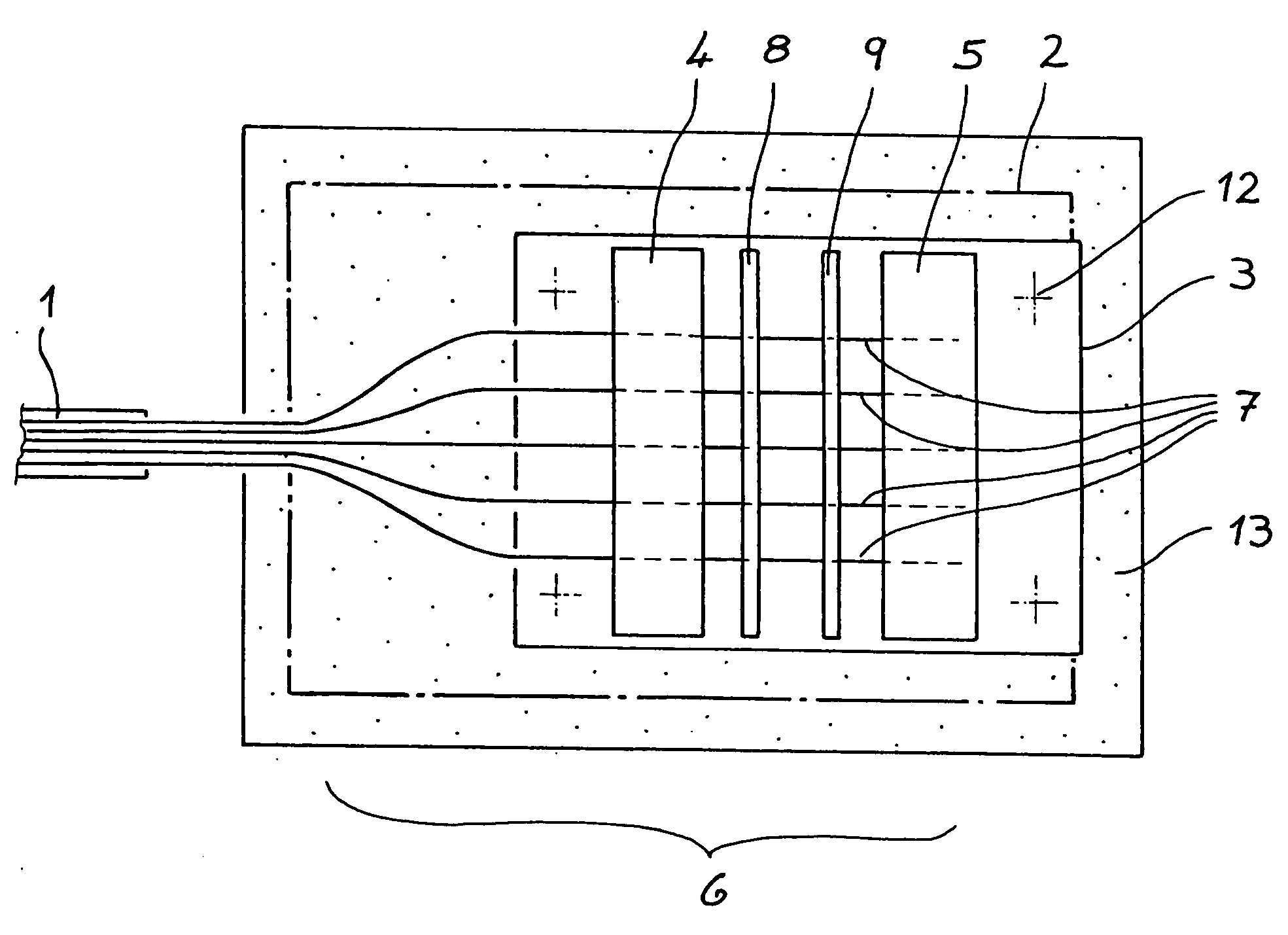
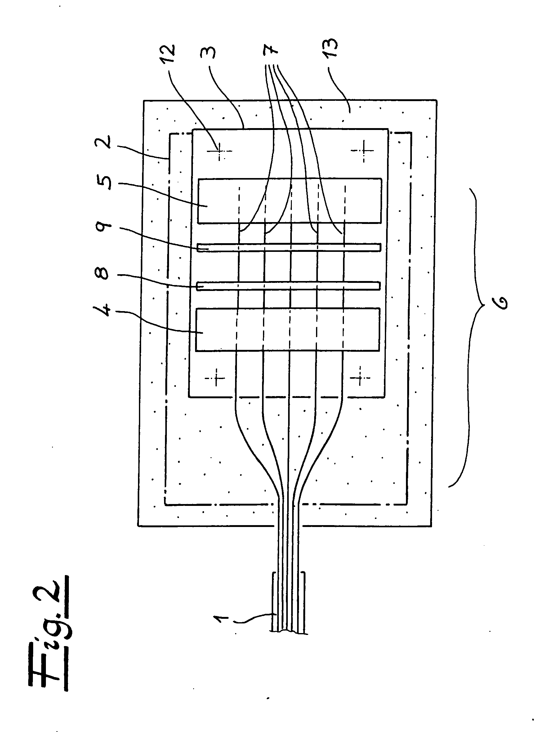
[0030]In the figures, an explosion-protected plug-in connector is shown, in other words a plug-in connector that ensures, in an area at risk of explosion, that a network cable 1 or a network 1 can be connected with an electrical device 2 or a circuit board 2 of the electrical device in question. For this purpose, the plug-in connector is fundamentally equipped with a housing 3 and at least one electrical connector unit 4, 5. At least one conductor end section 6 of the network or network cable 1 engages into this electrical connector unit 4, 5.

[0031]In particular from the top view according to FIG. 2, one can see that the conductor end section 6 of the network or the network cable 1 is composed of a plurality of individual leads 7, which are contacted using the electrical connector unit 4, 5. In the exemplary embodiment, the electrical connector unit 4, 5 is a first IDC terminal unit 4 and a second IDC terminal unit 5. Fundamentally, even more than these two IDC terminal units 4, 5 c...


PUM


Abstract

An explosion-protected plug-in connector, particularly for coupling of a VoIP telephone with a network, has at least one housing and at least one first electrical connector unit in the housing. At least one conductor end section of the network engages into the connector unit. Supplemental to the first electrical connector unit, which is configured as an IDC terminal unit, there is at least one further second IDC terminal unit provided in the housing. The conductor end section engages into the two IDC terminal units. A hold-down disposed between the two IDC terminal units is provided for the conductor end section.

Description

CROSS REFERENCE TO RELATED APPLICATIONS[0001]Applicants claim priority under 35 U.S.C. §119 of German Application No. 20 2011 000 836.3 filed Apr. 8, 2011, the disclosure of which is incorporated by reference.BACKGROUND OF THE INVENTION[0002]1. Field of the Invention[0003]The invention relates to an explosion-protected plug-in connector, particularly for coupling of a VoIP telephone with a network. The connector has least one housing, and at least one first electrical connector unit in the housing. At least one conductor end section of the network engages into the electrical connector unit.[0004]2. The Prior Art[0005]U.S. Pat. No. 4,741,031 describes an explosion-protected telephone that is coupled with a network by way of an electrical connector unit. In this connection, a special interface is implemented.[0006]Explosion-protected plug-in connectors or explosion-protected devices in general have great mechanical safety and avoid the formation of sparks. For this reason, there are s...

Claims


Application Information

Patent Timeline
IPC IPC(8): H01R12/53H01R4/24
CPCH01R4/2416H01R2201/16H01R13/53
Inventor MERTZ, MARTINKANTY, GEORG KARLBEHNISCH, BODO
Owner FHF FUNKE HUSTER FERNSIG
Learn More