Tracking and monitoring camera device and remote monitoring system using same

Inactive Publication Date: 2012-10-11
YOUNG KOOK ELECTRONICS
View PDF7 Cites 45 Cited by
  • Summary
  • Abstract
  • Description
  • Claims
  • Application Information

AI Technical Summary

Benefits of technology

[0021]The camera apparatus according to the present invention includes a first camera unit, i.e., a wide area monitoring camera, and a second camera unit, i.e., an intensive monitoring camera, as one body, and accordingly, the camera apparatus can smoothly monitor an overall situation of a wide area and intensively monitor and trace a specific area or a target object. Since three steps of pattern monitoring including “entire area monitoring”, “intensive monitoring”, and “automatic trace” are sequentially and simultaneously performed, the apparatus and system of the present invention may perform an operation close to “monitoring based on intelligence and visual observation of a human being”, and thus a perfect monitoring function can be implemented.
[0022]In addition, trace of a moving object is performed not by a remote control apparatus in a central motoring room, but by a camera apparatus, and thus although power of the central motoring room is cut off or an error occurs at the remote control apparatus or a communication line, tracing and monitoring can be continued without interruption.
[0023]Since the lens of a wide area monitoring camera is disposed on the outer surface of the housing to direct the optical axis of the lens toward the lower outside, a shadow area is not generated in a neighboring area including an area directly below the camera apparatus. At the same time, since the wide area monitoring camera and the intensive monitoring camera do not interfere with each other, a range of vision can be secured to the maximum.
[0024]Particularly, according to a preferred embodiment of the present invention, since the camera apparatus has a small volume and a compact form, manufacturing cost is low, and its appearance is not spoiled while being harmonized with the installation environment. In addition, the camera apparatus is not easily spotted by a potential intruder who tries to avoid or detour a monitoring system.

Problems solved by technology

However, since lenses employed in the PTZ camera apparatus do not have a wide view angle, there may be a blind spot that the camera apparatus cannot observe depending on a monitoring direction set by the operator.
Particularly, when the camera apparatus zooms in the lens and drives a panning and tilting mechanism to trace and monitor a specific target, the camera apparatus cannot monitor other than the neighboring areas of the traced target.
However, in the case of a camera apparatus using the fisheye lens, a photographed image is round-shaped, and thus distortion is severe overall, and particularly it is difficult to identify a thing at the edge of the image.
However, the dual camera apparatus specified in the above-identified reference has a very complicated structure in contrast to the original intention of the inventors, and thus processing and assembling efforts cannot but increase.
Furthermore, since the first camera is provided at the lower center of the dual camera apparatus, the first camera blocks the view of the second camera or hinders left and right or up and down movement of the second camera.
Accordingly, if the intruder is positioned beneath the center of the dual camera, the second camera cannot properly photograph the intruder.
However, in the apparatus specified in the reference described above, since the plurality of component cameras and the PTZ camera are separately manufactured and installed on the supporting bar, the size of the camera apparatus increases, and furthermore, limitations caused by the installation space or method are increased.
In addition, in such a system, the plurality of component cameras functions only as a sensor and almost cannot grasp continuous moving routes of a moving object from the images acquired by the component cameras.

Method used


Image

  • Tracking and monitoring camera device and remote monitoring system using same
  • Tracking and monitoring camera device and remote monitoring system using same
  • Tracking and monitoring camera device and remote monitoring system using same

Examples


Embodiment Construction

Technical Problem

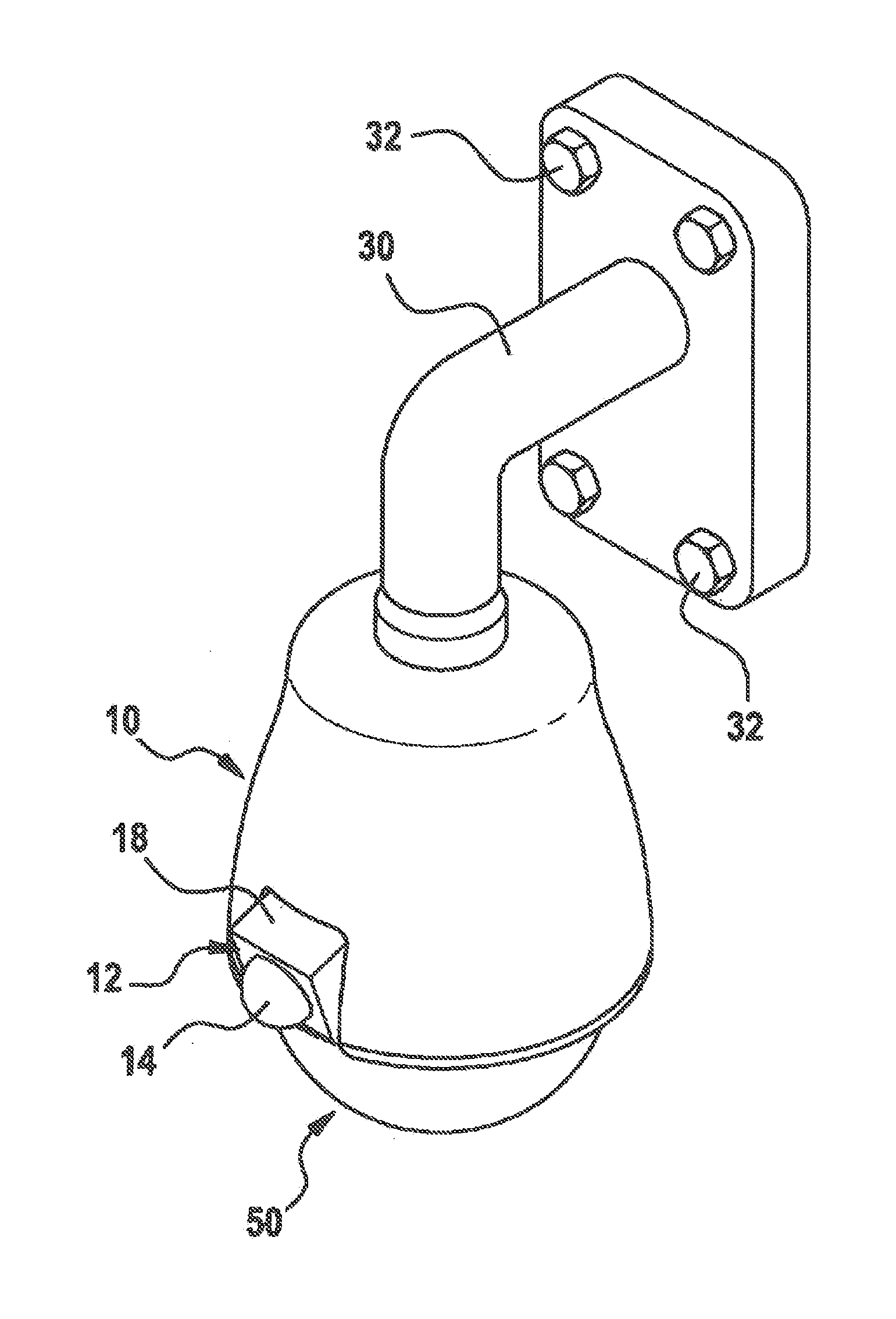
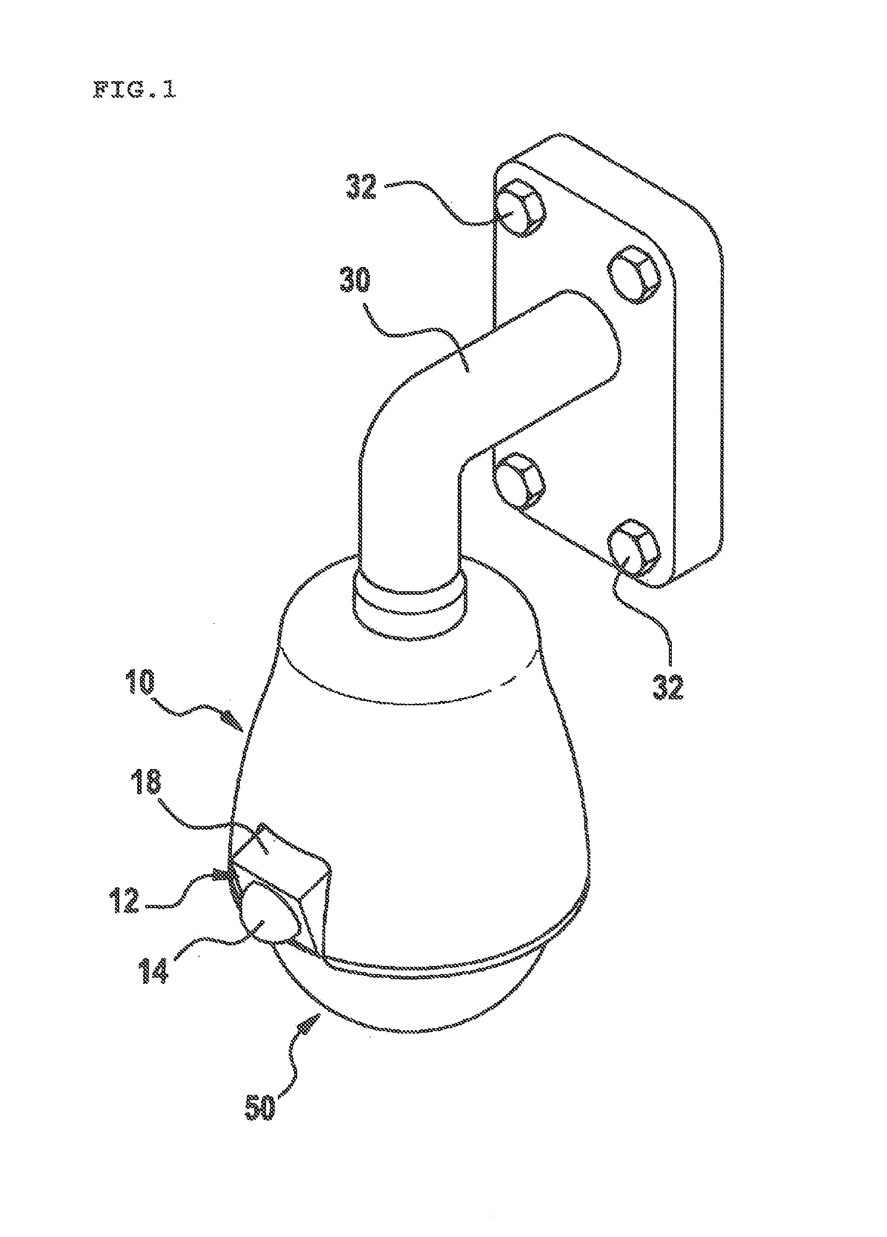
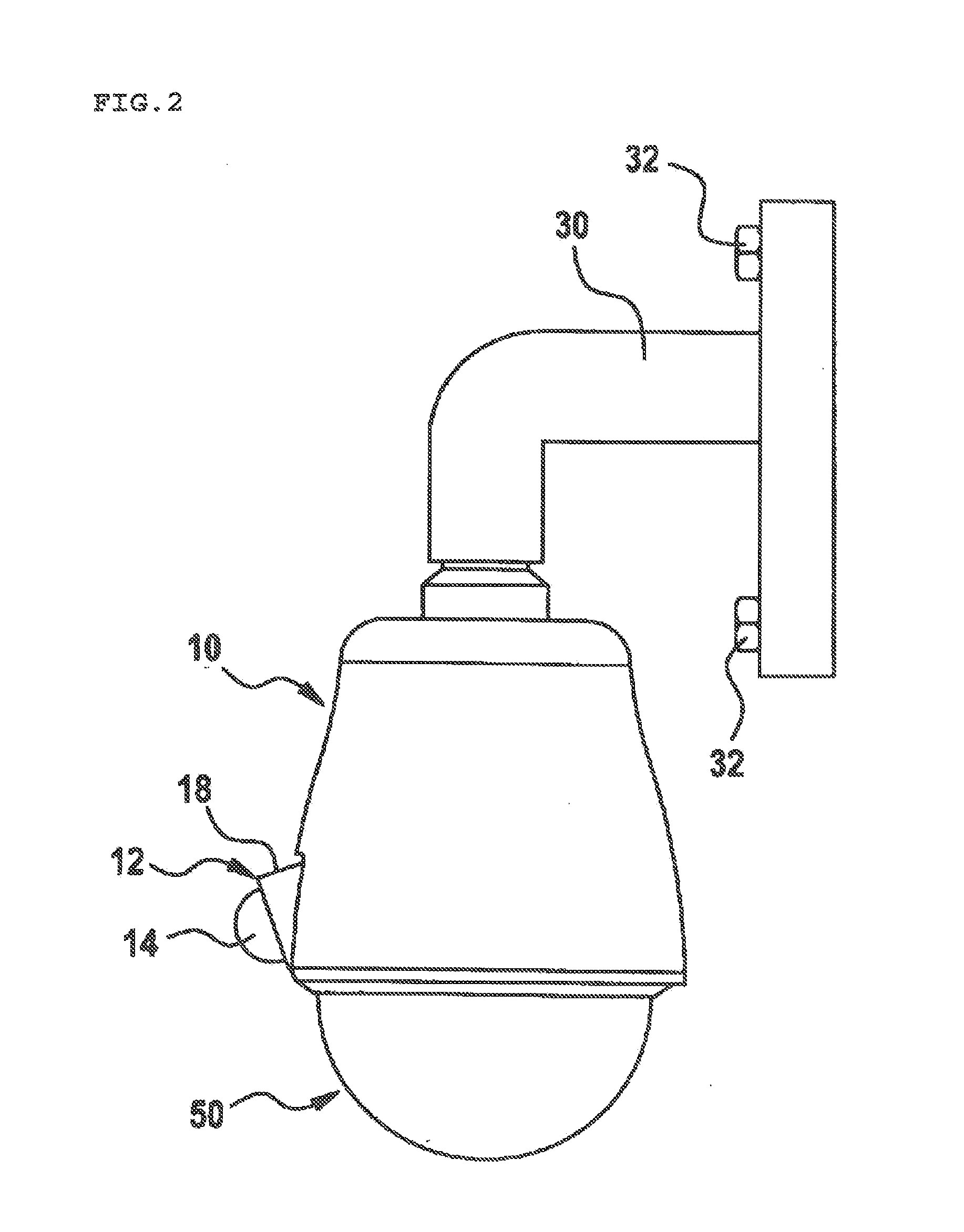
[0011]The present invention has been made in view of the above problems, and it is an object of the present invention to provide a camera apparatus including a wide area monitoring camera and an intensive monitoring camera as one body, in which the camera apparatus can smoothly monitor an overall situation of a wide area and intensively monitor and trace a specific area or a target object, and a shadow area is not generated in an area directly below the camera apparatus.

[0012]In addition, another object of the present invention is to provide a monitoring system capable of smoothly monitoring an overall situation of a wide area and intensively monitoring and tracing a specific area or a target object by employing such a camera apparatus.

Technical Solutions

[0013]To accomplish the above object, according to one aspect of the present invention, there is provided a camera apparatus including a main frame, a first camera unit and a second camera unit. The main frame has a...


PUM


Abstract

A camera apparatus including a wide area monitoring camera and an intensive monitoring camera as one body. The camera apparatus includes a main frame, a first camera unit and a second camera unit. The main frame has a lens installation surface where a normal line is directed to the lower outside. The first camera unit is installed in the main frame, has a wide angle lens disposed on the lens installation surface so as to direct an optical axis to lower outside and a first image sensor for converting light entering through the wide angle lens into an electrical signal, and photographs images of neighboring areas including an area directly below the camera apparatus. The second camera unit has a second image sensor and is installed so as to rotate horizontally and vertically with respect to the main frame.

Description

FIELD OF THE INVENTION[0001]The present invention relates to a television camera apparatus, more particularly to a multi-functional monitoring camera apparatus provided with a plurality of cameras. In addition, the present invention relates to a remote monitoring system employing such a camera apparatus.BACKGROUND OF THE RELATED ART[0002]Security and monitoring systems using monitoring camera apparatuses are widely used for entrance management or security purposes. Installation of such security and monitoring systems continues to grow even on general roads or in residential areas, as well as in banks, military facilities and other public facilities or business buildings where security is required.[0003]Although various kinds of monitoring camera apparatuses are used, one of the most widely used camera apparatuses at the moment when the present application is prepared is a speed dome camera apparatus of a Pan-Tilt-Zoom (hereinafter, referred to as PTZ) method capable of horizontal ro...

Claims


Application Information

Patent Timeline
IPC IPC(8): H04N7/18G03B19/00G03B30/00
CPCG08B13/19626G08B13/1963G08B13/19632H04N5/23238H04N5/247H04N7/181G08B13/19643H04N23/698H04N23/90
Inventor KIM, BAE HOONLEE, JEE HWAN
Owner YOUNG KOOK ELECTRONICS
Why Eureka
Try Eureka