
Brushless Electric Motor

a brushless electric motor and motor housing technology, applied in the direction of supporting/enclosing/casing, electrical equipment, manufacturing dynamo-electric machines, etc., to achieve the effect of reliable flanging of the motor housing, low notch load, and high mechanical loadability of the housing

Inactive Publication Date: 2012-10-11
BADER HANS +1
View PDF6 Cites 3 Cited by
  • Summary
  • Abstract
  • Description
  • Claims
  • Application Information

AI Technical Summary

Benefits of technology

[0013]By way of contrast, the task of the present invention is to develop further a brushless electric motor in an appropriate manner such that the motor meets the aforementioned requirements and to provide an electric motor which is especially compact, reliable and can be produced at a reasonable price as well as to provide a housing for such a brushless electric motor and a method of producing such a brushless electric motor.
[0036]In a further advantageous development in particular the cover sections can be provided with venting slots for cooling the drive components, in particular the stator assembly. In addition, motors with a relatively high power input and relatively long duty cycles can be provided with a forced cooling via an air supply unit which is driven by an armature shaft and can, in particular, be used for cooling the stator assembly especially effectively. In this way, cooling the motor can be further improved in addition to the heat dissipation via the housing surface and in particular the temperature of the stator windings can be reduced which makes possible a higher power density of the motor while the construction size is reduced at the same time. Furthermore, the necessity of the transmural heat transfer via the motor housing has to be taken into account only slightly or not at all.

Problems solved by technology

Furthermore, they can achieve higher efficiencies and the danger of fire caused by sparks due to brush sparking does not apply.

Method used


Image

  • Brushless Electric Motor
  • Brushless Electric Motor
  • Brushless Electric Motor

Examples


first embodiment

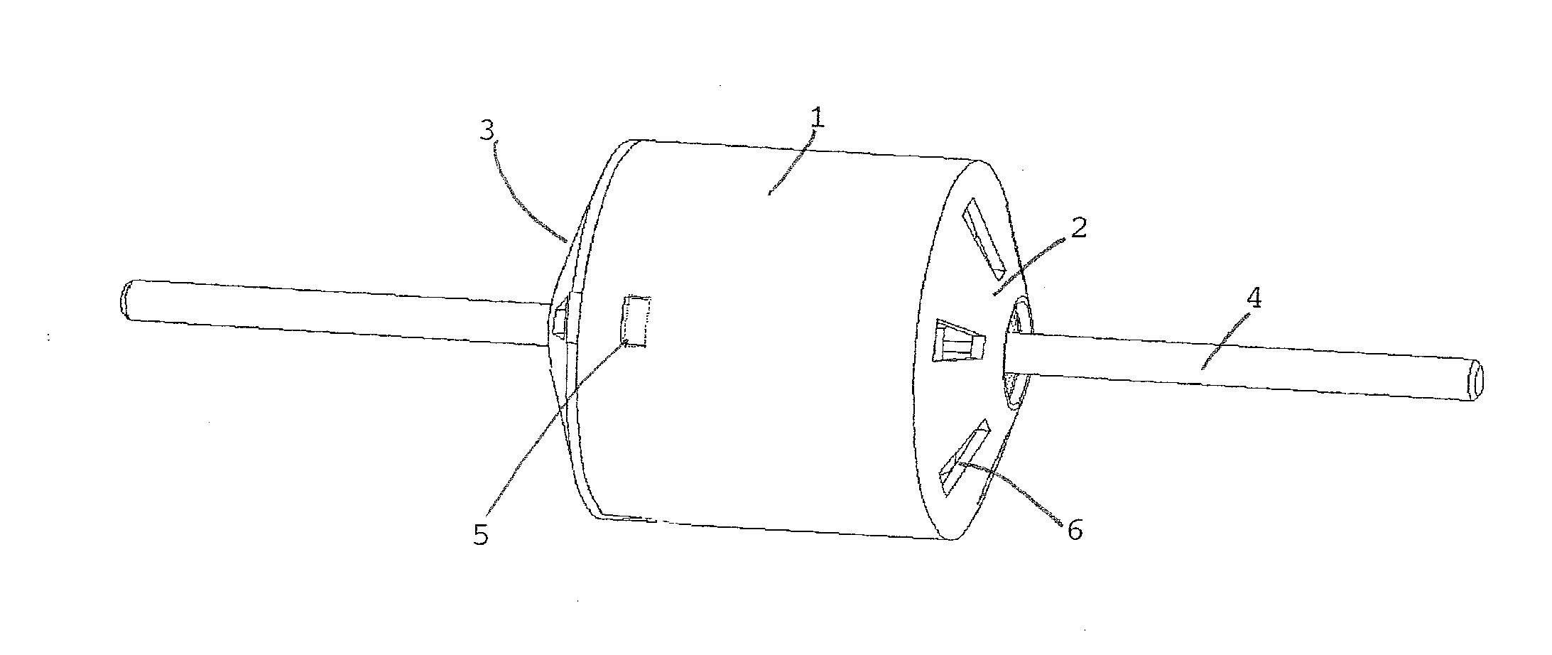
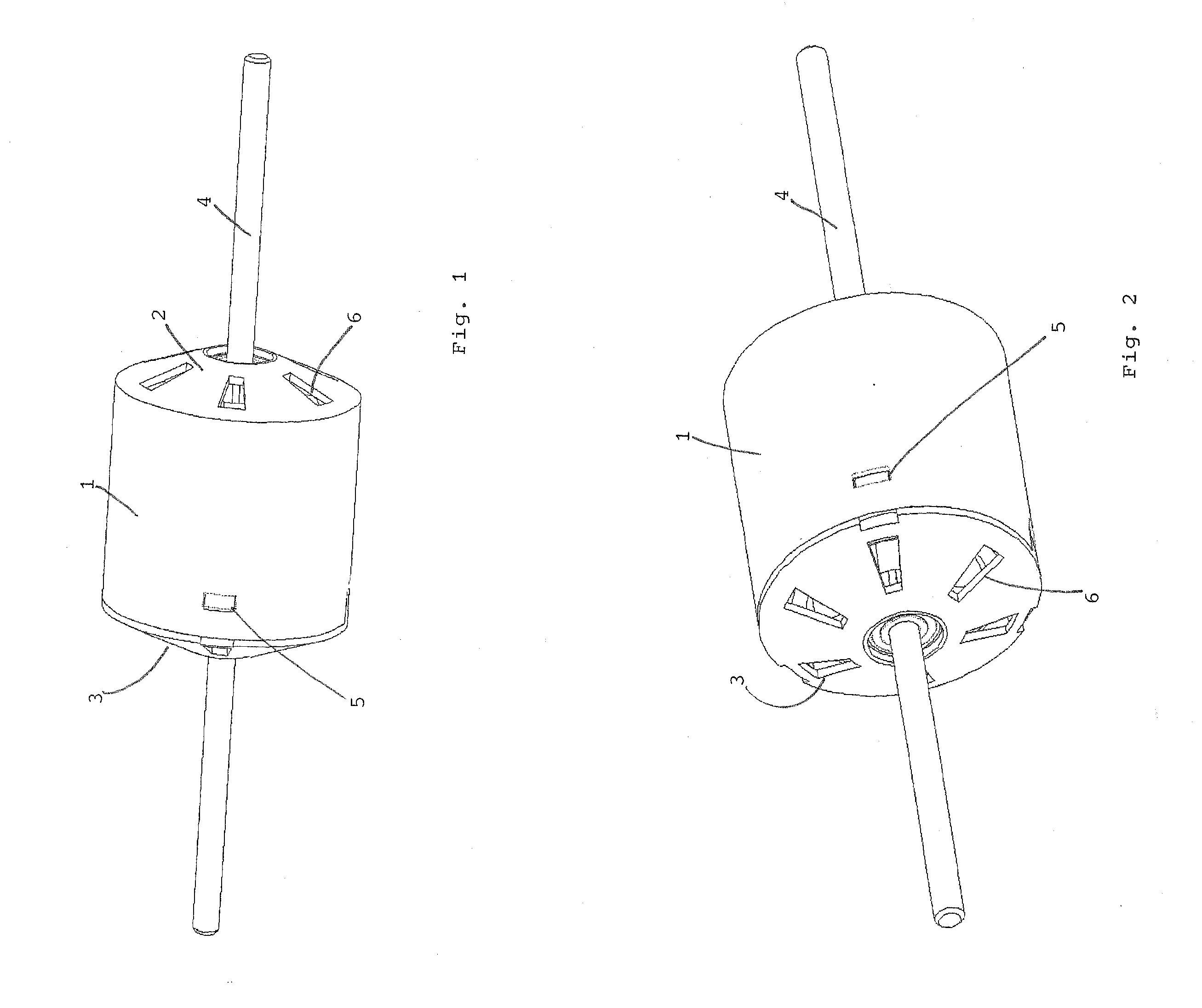
[0043]FIGS. 1 and 2 show oblique views of a brushless electric motor with housing from two different perspectives. This is an embodiment in which the housing is provided with a first cover section 2 which is integrally adapted to the casing section I as well as a second cover section 3 locked in place. The armature shaft is provided with reference number 4 and passes through both sides of the housing. Furthermore, the locking openings 5 can be seen in the casing section 1 of the housing; the snap-in tongues of the snapped-in cover section 3 which are not displayed in these figures form a positive connection with the locking openings. Both cover sections 2 and 3 are provided with six venting openings each for cooling, in particular, the current-carrying stator assembly (not shown) of the brushless electric motor.

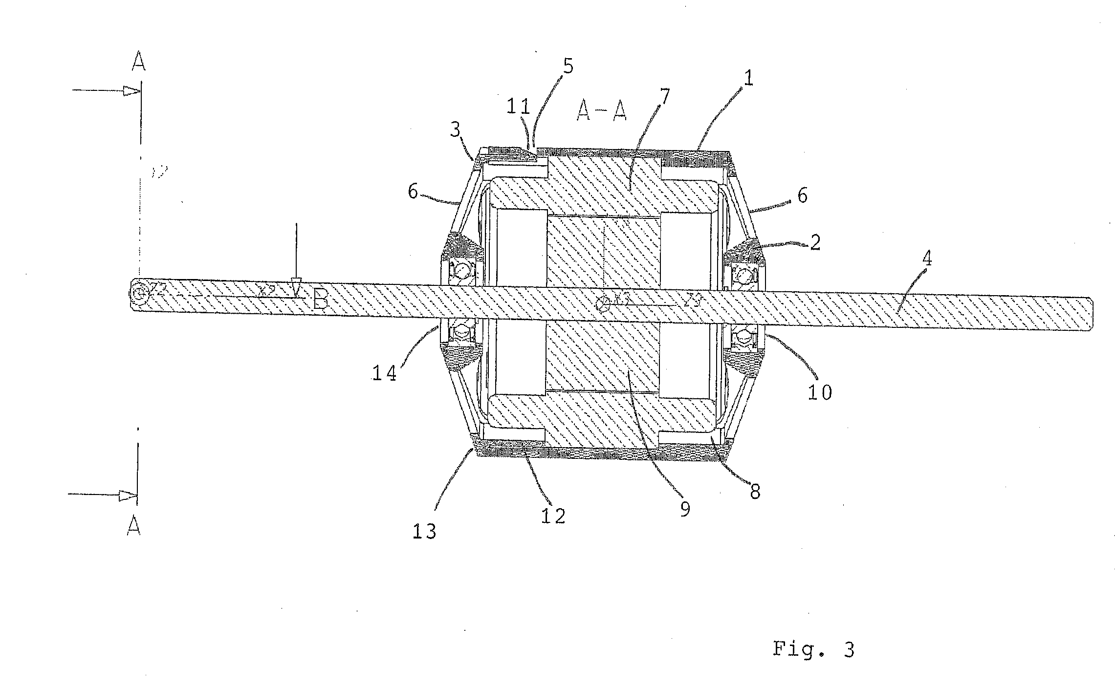
[0044]FIG. 3 shows a cross-sectional view of this brushless electric motor according to the first embodiment. The casing section I of the housing surrounds the stator assemb...

second embodiment

[0047]FIG. 4 is an exploded view of a brushless electric motor according to a This embodiment is provided with a casing section 1 onto which lockable cover sections 3 can be snapped-in on both sides. The motor, in turn, is provided with an armature shaft 4 to which the rotor 9 with the permanent magnets 17 is attached. As shown, the stator assembly 7 with the windings 16 surrounds the rotor and, when fully assembled, meshes with the molded bodies 8 and keeps them in position axially as well as radially.

[0048]Reference number 14 represents both ball bearings which, when fully assembled, are connected to the respective cover section 3 via a snap-in connection. The casing section 1 is provided with recesses 5 which, when fully assembled, are connected to the snap-in tongues 11 of the cover sections 3 via a snap-in connection. Furthermore, the casing section 1 is provided with structural elements 15 in the form of axially extending ribs which serve as reinforcement elements of the hous...


PUM

PropertyMeasurementUnit
poweraaaaaaaaaa
durableaaaaaaaaaa
axial lengthaaaaaaaaaa

Abstract

The invention relates to a brushless electric motor—preferably for a vehicle fan—having an armature which is supported on both sides in a housing, wherein the housing consists substantially of a plastic-containing material and is provided with a preferably substantially tapered casing section as well as two cover sections onto or into both cover sections one bearing each is formed for the armature shaft, and said two cover sections being connected to each other via the casing section and being supported by each other, as well as a stator assembly which extends between the housing casing and the armature wherein the housing is further provided with at least one molded body made of a plastic-containing material for receiving the stator assembly while at the same time determining the axial and radial position, said molded bodies, in turn, being clamped between the cover sections and the casing section in a radial and axial direction, and in this way reinforcing the housing.

Description

TECHNICAL FIELD[0001]The invention relates to a brushless electric motor as used, for instance, as a fan motor for vehicles such as cabin scooters, buses or other large capacity vehicles as well as to a housing for such a brushless electric motor as well as to a method of producing such a brushless electric motor.CROSS-REFERENCE TO RELATED APPLICATIONS[0002]This application claims foreign priority benefits under 35 U.S.C. .§.119 to German Patent Application No. 10 2011 006 893.7 filed on Apr. 6, 2011 the entire contents of which are hereby incorporated by reference.BACKGROUND OF THE INVENTION[0003]Brushless electric motors have long been known in drive technology and have stood the test of time as they are highly reliable, durable and hardwearing and as they can do without sliding contacts and mechanical commutators. Furthermore, they can achieve higher efficiencies and the danger of fire caused by sparks due to brush sparking does not apply.[0004]Thus, DE 1 233 480 B1 describes a b...

Claims


Application Information

Patent Timeline
Patent Type & Authority Applications(United States)
IPC IPC(8): H02K5/15H02K15/00
CPCH02K1/185Y10T29/49009H02K5/08
Inventor BADER, HANSKEILBACH, CHRISTIAN
Owner BADER HANS
Learn More