
System, method and apparatus for protecting downhole components from shock and vibration

a technology for protecting downhole components and equipment, applied in the direction of shock absorbers, borehole/well accessories, survey, etc., can solve the problems of damage to or failure of downhole components, equipment may be subjected to high temperatures, 150° c, etc., and achieve the effect of increasing the penetration ra

Inactive Publication Date: 2012-10-04
PHOENIX TECH SERVICES LP
View PDF3 Cites 51 Cited by
  • Summary
  • Abstract
  • Description
  • Claims
  • Application Information

AI Technical Summary

Benefits of technology

[0008]In still other embodiments, an agitator drilling assembly may comprise a drill string; an agitator mounted in the drill string to vibrate and increase penetration rate while drilling; a MWD tool having a plurality of components mounted in the drill string; and snubber shock assemblies mounted in the drill string between at least some of the components of the MWD tool such that the snubber shock assemblies are mounted inside the MWD tool, and said at least some of the components float axially and are protected from shock and vibration.

Problems solved by technology

However, these devices can cause damage to or the failure of the downhole components, such as the sensitive electronic components of MWD systems.
Moreover, the equipment may be subjected to high temperatures in the range of 150° C. as well as g-force vibration and shock on the order of 100 g in amplitude.
These systems also tend to be over-damped and are so stiff that they have virtually no shock absorbing capability.

Method used


Image

  • System, method and apparatus for protecting downhole components from shock and vibration
  • System, method and apparatus for protecting downhole components from shock and vibration
  • System, method and apparatus for protecting downhole components from shock and vibration

Examples


Embodiment Construction

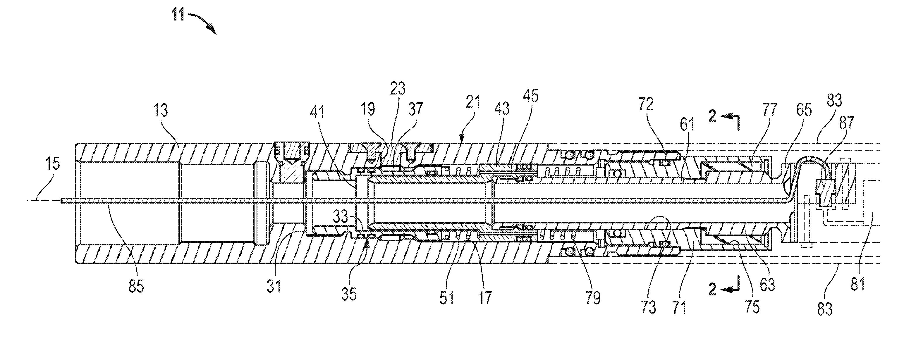
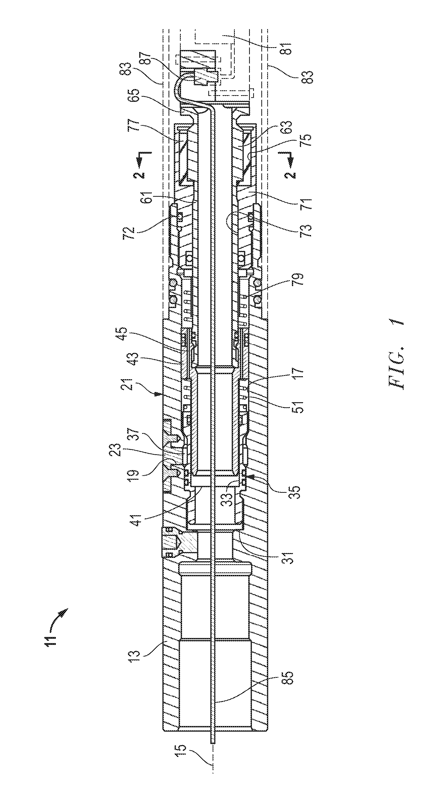
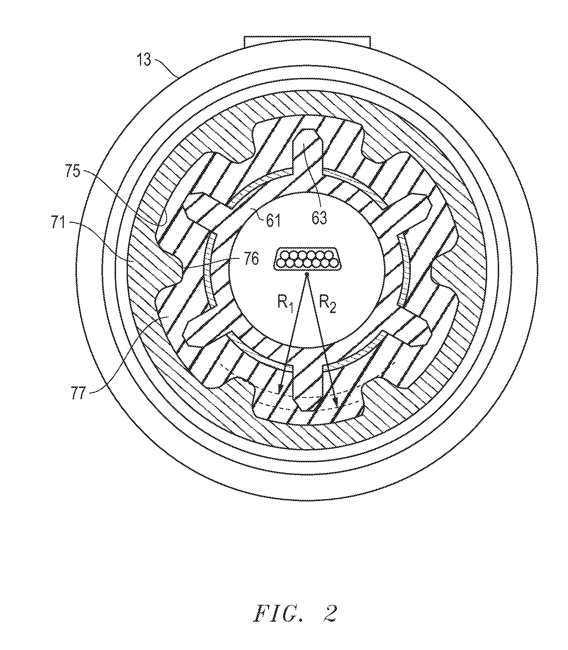
[0017]Embodiments of a system, method and apparatus for protecting MWD equipment from shock and vibration are disclosed. For example, FIGS. 1 and 2 illustrate one embodiment of snubber shock assembly 11. Snubber shock assembly 11 may comprise a housing 13 having an axis 15, an axial passage 17, a fill port 19 extending from an exterior 21 of the housing 13 to the axial passage 17, and an fluid fill cover 23 mounted and sealed to the fill port 19 as shown.

[0018]A bushing or seal housing 31 may be mounted in and coaxial with the axial passage 17 of the housing 13. The seal housing has a piston bore 33 and an outer surface 35, and at least a portion 37 of the outer surface 35 may be recessed adjacent the fill port 19.

[0019]The snubber shock assembly 11 may further comprise a piston 41 that is hollow and extends into the piston bore 33 of the seal housing 31 for coaxial reciprocal motion therein. In some embodiments, the piston has an axial travel range of approximately one inch (e.g., ...


PUM


Abstract

A downhole tool assembly has a component that is sensitive to shock and vibration. A reciprocating element is coupled to the component. The reciprocating element has an axial internal passage and an outer surface. A housing has an internal axial bore for receiving the reciprocating element for axial reciprocal motion therein. A retainer is mounted to the housing and seals the housing between the component and the reciprocating element. A first spring is located between the housing and the reciprocating element. A second spring is located between the reciprocating element and the retainer. A first reciprocating seal is located between the reciprocating element and the housing. A second reciprocating seal is located between the connector and the retainer. A fluid is contained by the reciprocating seals inside the housing. The reciprocating element permits a limited amount of fluid to flow between sides thereof.

Description

BACKGROUND OF THE INVENTION[0001]1. Field of the Disclosure[0002]The present invention relates in general to protecting downhole components from shock and vibration while drilling a well and, in particular, to a system, method and apparatus for protecting measurement while drilling (MWD) equipment from shock and vibration.[0003]2. Description of the Related Art[0004]Some oil and gas exploration and production companies use vibrating devices known as agitators to increase penetration rates while drilling wells. Agitators typically operate or reciprocate between about 12 and 26 hertz during drilling operations, and constantly vibrate at these frequencies. Accordingly, agitators provide additional shock and vibration throughout the drill string that improve drilling performance. However, these devices can cause damage to or the failure of the downhole components, such as the sensitive electronic components of MWD systems. Moreover, the equipment may be subjected to high temperatures in...

Claims


Application Information

Patent Timeline
IPC IPC(8): E21B41/00F16F7/00F16F13/00E21B47/00
CPCE21B47/011E21B17/07E21B7/24E21B47/017
Inventor CRAMER, DAVID S.DEVLIN, DAVID D.
Owner PHOENIX TECH SERVICES LP
Learn More