
Method for maintaining a vehicle air conditioning unit and service apparatus therefor

a vehicle air conditioner and air conditioning unit technology, applied in the direction of refrigeration machines, vehicle heating/cooling devices, refrigeration components, etc., can solve the problems of laborious and laborious search for leaks, and achieve the effect of reducing costs and improving the possibility of diagnosing

Active Publication Date: 2012-10-04
DOMETIC APPLIANCES
View PDF10 Cites 27 Cited by
  • Summary
  • Abstract
  • Description
  • Claims
  • Application Information

AI Technical Summary

Benefits of technology

[0009]The invention considerably improves the possibility of diagnosing the state of the vehicle air-conditioning system in the course of the occasional exchange of the refrigerant / compressor oil mixture. It is therefore possible, on the one hand, to determine whether the refrigerant loss which the closed refrigerant circulation system of the vehicle air-conditioning system has suffered since the last service has remained within the legal limits, for example below 40 gr or 60 gr. It is therefore possible to monitor compliance with legal limits.
[0010]If refrigerant losses which go beyond the natural refrigerant leakage quantities, which are almost unavoidable for structural reasons in vehicle air-conditioning systems, this may be due, inter alia, to leakage due to impacts by stones, material wear or component defects. In the past, no particular attention has been paid to this criterion. The emphasis was on recovering part of the refrigerant occurring due to expansion when the vehicle air-conditioning system is emptied, in order therefore to reduce costs to a certain extent. Conclusions about the state or type and extent of defects in the vehicle air-conditioning system, and in particular in the refrigerant circulation system, were possible only in a general way, in particular because the expansion behavior of the refrigerant / compressor oil mixture during the servicing of vehicle air-conditioning systems of different design or with different installation states can only be compared with one another with difficulty. By virtue of the invention, such partial quantities of refrigerant, which were not taken into account in the past, are also measured during the servicing of the vehicle air-conditioning system. The inventive combination of the emptying of the residual quantity from the coolant circulation system by means of a vacuum pump with subsequent further processing of the residual gases in the separator stage now provides greater insight into the state of the vehicle air-conditioning system. The invention also makes a contribution to environmental protection and / or to equipment safety and working safety because a servicing system which is closed with respect to the refrigerant is produced, with the result that environmentally damaging refrigerant or such refrigerant which is at risk of explosion or fire can be safely discharged.
[0012]In order to improve the diagnostic accuracy even further, it is proposed to temporarily fluidically connect a container which is connected downstream of the separator, for liquid components separated from the circulation mixture, such as compressor oil, to the suction side of the vacuum pump, and to feed non-condensed gas volumes occurring in this container to the separator stage again. In this way, residual quantities of refrigerant which are discharged together with the used compressor oil from the separator and residual quantities of refrigerant which are still dissolved to a certain extent in the compressor oil can also be detected. The switchover can be triggered, inter alia, by pressure occurring in the container.
[0018]In order to protect the refrigerant compressor against damage, the refrigerant compressor oil mixture which flows out of the vehicle air-conditioning system in the first servicing phase is firstly heated in order to vaporize the refrigerant and prevent fluid refrigerant still passing into the refrigerant compressor. For this purpose, a heat exchanger is provided. This may use the compression heat of the refrigerant compressor for heating because the gaseous refrigerant which flows to the refrigerant compressor is heated considerably by the compression without condensing.

Problems solved by technology

If refrigerant losses which go beyond the natural refrigerant leakage quantities, which are almost unavoidable for structural reasons in vehicle air-conditioning systems, this may be due, inter alia, to leakage due to impacts by stones, material wear or component defects.
Conclusions about the state or type and extent of defects in the vehicle air-conditioning system, and in particular in the refrigerant circulation system, were possible only in a general way, in particular because the expansion behavior of the refrigerant / compressor oil mixture during the servicing of vehicle air-conditioning systems of different design or with different installation states can only be compared with one another with difficulty.
If relatively large discrepancies in the quantities of refrigerant were found in the past in known servicing devices for vehicle air-conditioning systems, this automatically triggered extensive and laborious operations for searching for leaks which, as it were, were necessary purely through suspicion.

Method used


Image

  • Method for maintaining a vehicle air conditioning unit and service apparatus therefor
  • Method for maintaining a vehicle air conditioning unit and service apparatus therefor

Examples


Embodiment Construction

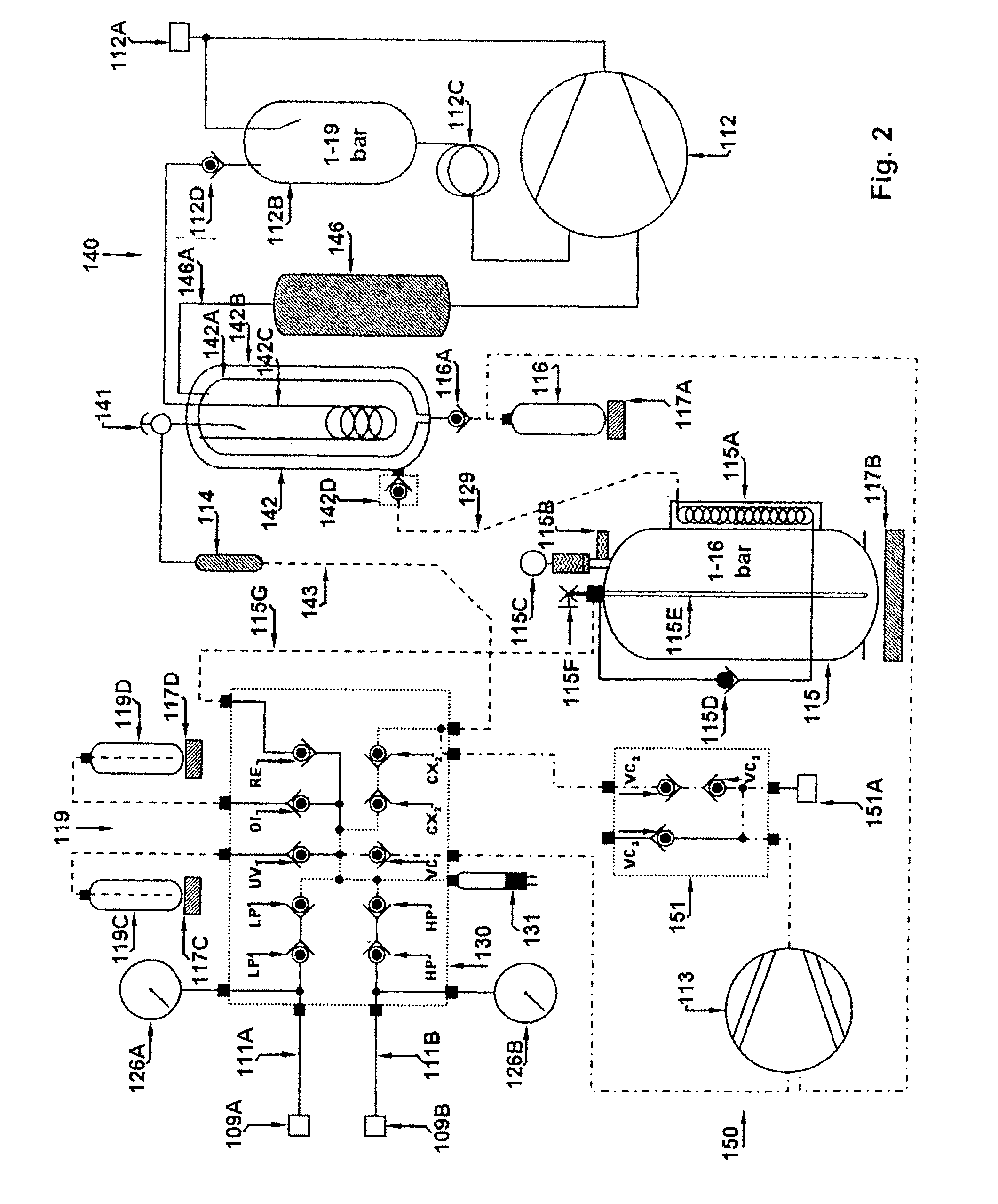
[0022]The block circuit diagram shows the basic design of a servicing device for vehicle air-conditioning systems. Accordingly, servicing connectors 109A, 109B for connection to the refrigerant / compression circuit of a vehicle air-conditioning system (not illustrated here) are provided in order to service the latter, in particular to empty and refill it. There is a fluidic connection via pressure hoses 111A, 111B to a first switchover valve block 130 whose function is explained further below. The switchover valve block 130 is fluidically connected, on the one hand, to a separator stage 140 which is illustrated on the right in the image and will be explained further below, and on the other hand (bottom left in the diagram) to a vacuum unit 150, which will also be explained further below. A low-pressure manometer 126A and a high-pressure manometer 126B on the switchover valve block 130 serve, inter alia, for checking the state and function of the coolant compressor oil circuit of the ...


PUM


Abstract

A method for servicing a vehicle air-conditioning system operated with a closed coolant circulation system, in which in a first servicing phase, a circulation mixture of refrigerant, compressor oil and, if appropriate, further mixture components is sucked out from a vehicle air-conditioning system into a separator stage by means of a compressor via a separator and in the process refrigerant is separated from the sucked-out circulation mixture by means of the separator, compressed and collected, and its quantity is determined. In a second servicing phase, the refrigerant circulation system of the vehicle air-conditioning system is largely emptied of residual content by means of a vacuum pump. The residual gases which are pumped out in the second servicing phase are conducted through the separator stage by means of the compressor, and the quantity of residual refrigerant collected in the process is determined.

Description

BACKGROUND OF THE INVENTION[0001]The invention relates to a method for servicing a vehicle air-conditioning system with a closed refrigerant circulation system according to the preamble of claim 1 and to a servicing device for same according to the preamble of claim 10. Accordingly, a vehicle air-conditioning system is serviced in two phases. In a first phase, the circulation mixture of refrigerant, compressor oil and, if appropriate, further mixture components is sucked out of the refrigerant circulation system of the vehicle air-conditioning system into a separator stage by means of a refrigerant compressor via a separator. In this context, refrigerant is separated from the sucked-out circulation mixture by means of the separator, compressed and collected, and its quantity is determined. In a second servicing phase, the refrigerant circulation system of the vehicle air-conditioning system is largely emptied of residual content by means of a vacuum pump. A corresponding servicing d...

Claims


Application Information

Patent Timeline
Patent Type & Authority Applications(United States)
IPC IPC(8): F25B45/00
CPCB60H1/00585F25B2400/23F25B45/00
Inventor ESCH, FRANZ-JOSEF
Owner DOMETIC APPLIANCES
Learn More