
Materials and methods for improved bone tendon bone transplantation

a technology of bone tendon and material, applied in the field of material and method for improving bone tendon bone transplantation, can solve the problems of inability to achieve surgery, lack of flexibility and stability of the repaired joint, and difficulty in utilizing bone/tendon grafts, etc., and achieves the effect of convenient and efficient surgery

Inactive Publication Date: 2012-09-27
RTI BIOLOGICS INC
View PDF25 Cites 0 Cited by
  • Summary
  • Abstract
  • Description
  • Claims
  • Application Information

AI Technical Summary

Problems solved by technology

However, this technique is often not possible, especially when the damage to the ligament is extensive.
These conventional techniques are not without their shortcomings; in most cases, the repaired joint lacks flexibility and stability.
Despite these realized advantages, there have been some difficulties encountered with utilizing bone / tendon grafts.
For example, surgical procedures involving transplantation and fixation of these grafts can be tedious and lengthy.
Further, surgeons must establish a means of attaching the graft, which also takes up valuable surgery time.
Another difficulty associated with using bone / tendon grafts is that there is a limited supply and limited size range available.
This can result in a patient having to choose an inferior procedure simply based on the lack of availability of tissue.

Method used


Image

  • Materials and methods for improved bone tendon bone transplantation
  • Materials and methods for improved bone tendon bone transplantation
  • Materials and methods for improved bone tendon bone transplantation

Examples


example 1

Procedure for Harvesting of Crude BTB for Patellar Tendon Tibial Donor

[0036]A BTB was harvested according to the following procedure:

[0037]1. Using blunt and sharp dissection remove the three layers of connective tissue from the anterior portion of the tendon.

[0038]2. Using scalpel or scissors cut along the medial and lateral borders of the tendon. Use the scissors to bluntly dissect under the tendon to separate it from the fat layer.

[0039]3. Cut around the Patellar block to separate it form the proximal tibia and distal femur. Leave approximately 4 cm of quadriceps tendon attached to the patellar if required. If no quadriceps tendon attachment is specified then remove quadriceps from patellar completely using sharp dissection.

[0040]4. Pull tendon away from capsule and remove all excess adipose tissue to the point of tibial insertion.

[0041]5. With a saw make a transverse cut through approximately the tibial tuberosity about 30 mm from the tendon insertion point. Make a similar cut a...

example 2

Procedure for Forming Patellar Tendons with Preshaped Dowels for Patellar Tendon Tibial Donor

[0048]A BTB was harvested according to the following procedure:

[0049]1. Using blunt and sharp dissection remove the three layers of connective tissue from the anterior portion of the tendon.

[0050]2. Using a scalpel or scissors cut along the medial and lateral borders of the tendon to separate it from the fat layer.

[0051]3. Cut around the Patellar block to separate it from the proximal tibia and distal femur.

[0052]4. Pull tendon away from capsule and remove all excess adipose tissue to the point of tibial insertion.

[0053]5. With a saw make a transverse cut through the tibial tuberosity about 30 mm from the tendon insertion point. Make a similar cut just proximal to the insertion point removing the tibial plateau. Make another cut across the coronal plane 20-30 mm posterior from the insertion point.

[0054]6. With a saw square the sides of the tibia bone block.

[0055]7. With a saw cut and square ...


PUM


Abstract

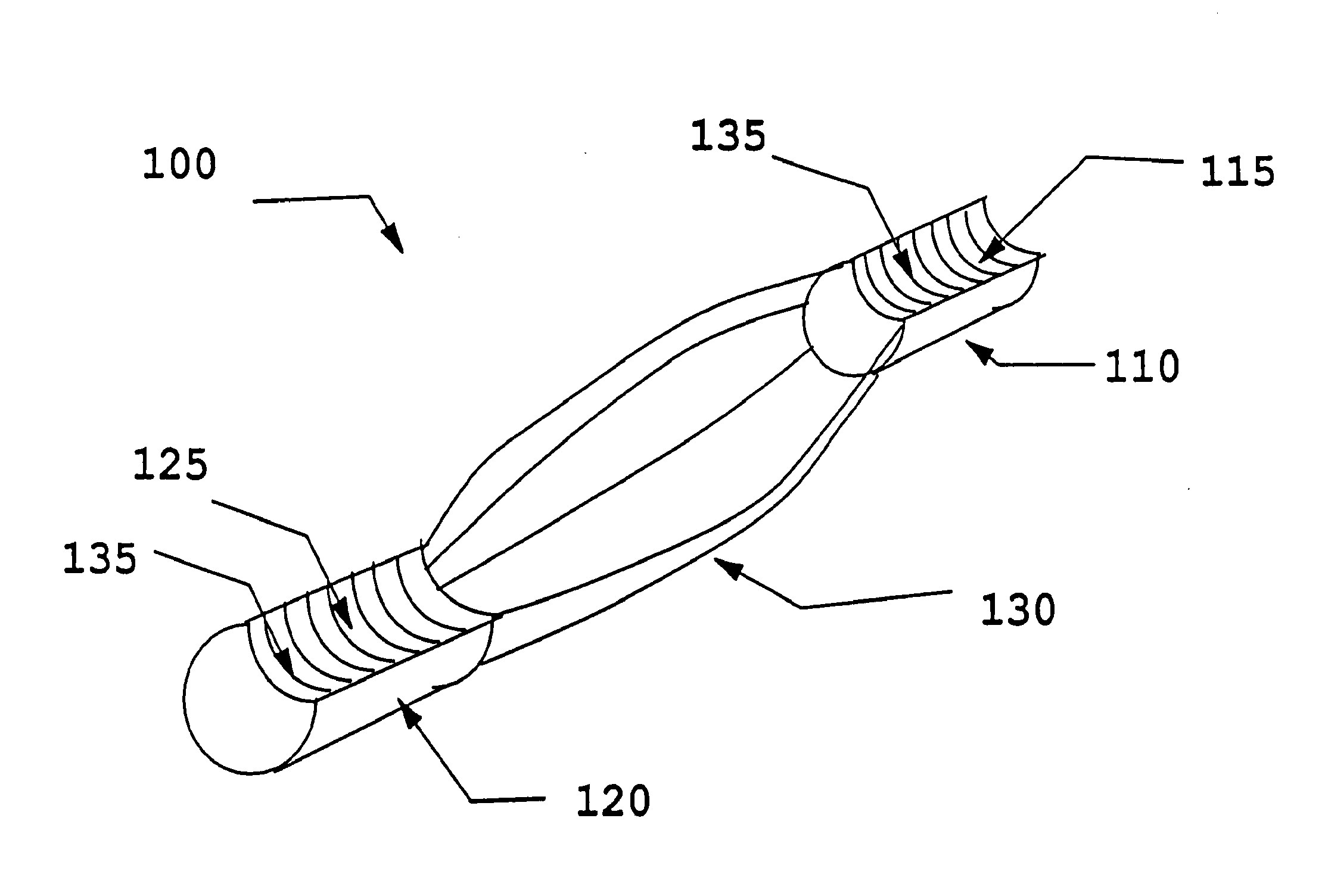
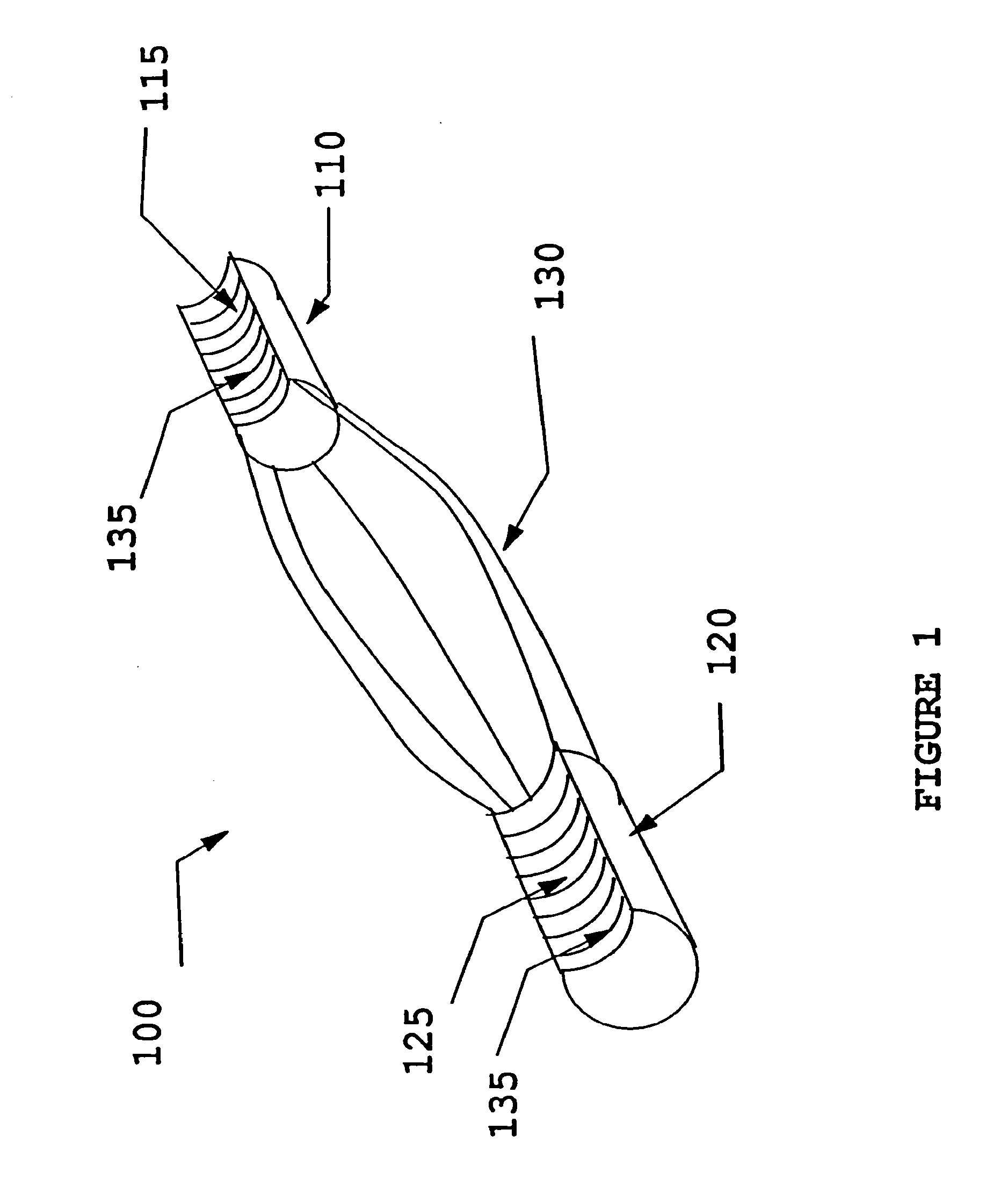
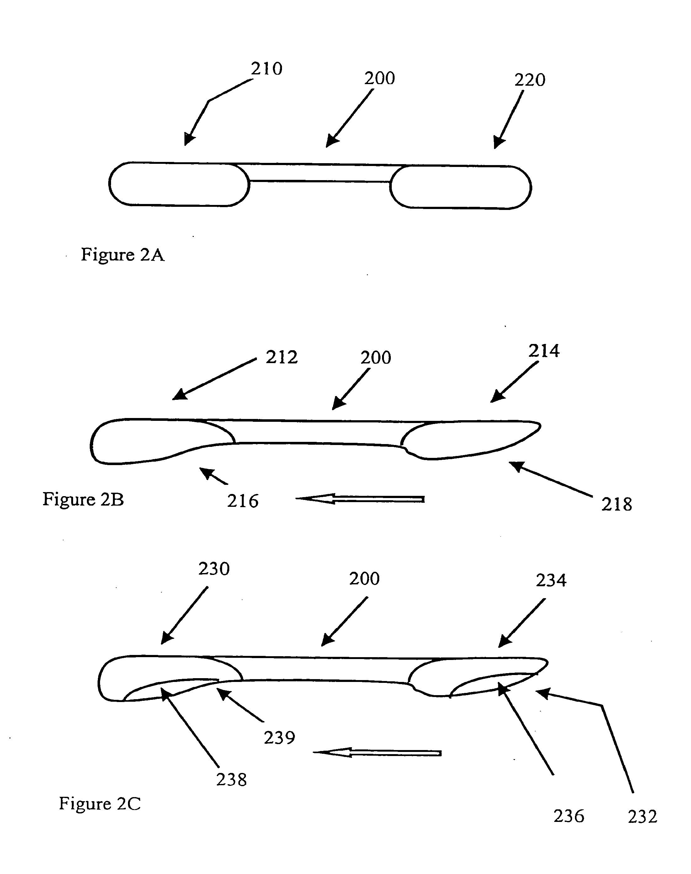
Disclosed herein is an improved Bone Tendon Bone graft for use in orthopedic surgical procedures. Specifically exemplified herein is a Bone Tendon Bone graft comprising one or more bone blocks having a groove cut into the surface thereof, wherein said groove is sufficient to accommodate a fixation screw. Also disclosed is a a method of harvesting grafts that has improved efficiency and increases the quantity of extracted tissue and minimizes time required by surgeon for implantation.

Description

[0001]The present application is a continuation of U.S. patent application Ser. No. 10 / 846,399 (now allowed), which was filed May 14, 2004, which is a continuation of U.S. patent application Ser. No. 09 / 528,034 (now U.S. Pat. No. 6,805,713), which was filed Mar. 17, 2000, which is a continuation-in-part of U.S. patent application Ser. No. 09 / 481,319 (now U.S. Pat. No. 6,497,726), which was filed Jan. 11, 2000. The entire text of the aforementioned applications is incorporated herein by reference in its entirety.BACKGROUND OF THE INVENTION[0002]Orthopedic medicine is increasingly becoming aware of the vast potential and advantages of using bone / tendon / bone grafts to repair common joint injuries, such as Anterior Cruciate Ligament (ACL) or Posterior Cruciate Ligament (PCL) tears. One technique that is currently used for repairing these types of injuries involves surgically reconnecting the torn portions of a damaged ligament. However, this technique is often not possible, especially w...

Claims


Application Information

Patent Timeline
Patent Type & Authority Applications(United States)
IPC IPC(8): A61F2/08A61B17/56A61B17/16A61F2/28A61F2/46
CPCA61B17/1635A61B17/1637A61B17/1675A61B2217/007A61F2/08A61F2002/4649A61F2002/0858A61F2002/087A61F2002/0882A61F2002/2839A61F2/0811A61F2230/0069A61F2310/00359
Inventor CARTER, KEVIN C.ESCH, MICHAELLAROCHELLE, PAULGROSS, JIM
Owner RTI BIOLOGICS INC
Learn More