Method for spinal drilling operation and guiding assembly

Inactive Publication Date: 2012-09-27
NAT CHENG KUNG UNIV
View PDF19 Cites 151 Cited by
  • Summary
  • Abstract
  • Description
  • Claims
  • Application Information

AI Technical Summary

Benefits of technology

[0015]In view of the foregoing subject, an objective of the present invention is to provide a guiding assembly for spinal drilling operation that includes a guiding element, an auxiliary element, a k-pin and a cannular driller. The guiding assembly is easily operated and has the specificity for patient's vertebra and high location stability and precision, so that it can improve the efficiency and application of the customized guiding element on the location and drilling / reaming issues during spinal drilling operation.
[0016]Another objective of the present invention is to provide a method for spinal drilling operation for operating the guiding element, auxiliary element, k-pin and cannular driller on set purpose and step by step so as to properly use the specific functions and the auxiliary properties of the elements, so that the operator can simply and rapidly perform the drilling operation and still keep the desired high location stability and precision.
[0035]As mentioned above, the guiding assembly for spinal drilling operation of the present invention is composed of several elements, including the guiding element, auxiliary element, k-pin and cannular driller, so that the stability and precision of the reaming procedure during the spinal drilling operation can be enhanced.
[0036]Moreover, the specific functions of the above elements can help the spinal drilling operation. Regarding to the guiding element, since it has simple structure and is suitable for customization, the demand of the patient can be satisfied. Besides, the guiding element has a portion fitting the vertebra, so that the connection between the guiding element and the vertebra can be further improved. In addition, the auxiliary element and the cannular driller are configured cooperating with the locating part. The auxiliary element can assist the location of the k-pin and prevent the non-stability in the conventional hand-hold procedure. The cannular driller can perform the reaming process through the locating part, thereby increasing the precision and decreasing the safety of spinal drilling operation.
[0037]Compared with the conventional art, the present invention still remains the conventional advantages of customizable and easy operation, and can further provide higher location stability and precision due to the structural property of the guiding element. Furthermore, either the method of the guiding assembly for spinal drilling operation utilizes an auxiliary element for facilitating and adjusting the penetrating position of the k-pin. This configuration can precisely match the hole drilled by the cannular driller with the targeted pedicle, so that the surgeons can precisely drill into the center of the pedicle of the targeted vertebra.
[0038]Preferably, the guiding element of the present invention can have customized design based on the surface angle of the targeted vertebra (e.g. cervical, thoracic or lumber vertebra) of the patient. Accordingly, when the fixing portion is pressed so as to push the guiding element, the guiding element can be still fixed on the targeted vertebra firmly, thereby increasing the precision and safety of the spinal drilling operation.

Problems solved by technology

Unfortunately, if the deformation of any vertebral body of the vertebrae occurs, the nerve is possibly pressed, which may indirectly affect the organ, muscle and gland body connected to the nerve.
This undesired deformation can result a huge injury to human health.
However, the implantation of transpedicular screw still exists a certain possibility of complication, especially for the cervical and thoracic vertebrae operation.
This unpredictable risk of these surgeries really stops many patients.
Since the shape of each vertebra may different in different bodies, it has been an important issue of the surgery to precisely implant the transpedicular screw into the center of the pedicle of the targeted vertebra.
However, although the first type can achieve a good precision, it spends a lot time on registration.
These complex and extra procedures can interfere with the operation.
Although the above method can reduce the error in the operation, it has a problem in keeping the auxiliary stand at the desired position.
Thus, the auxiliary stand is easily swayed even the operator carefully holds it.
In addition, the guide of the auxiliary stand can provide the reference for the drilling location, but it may lose stability during the drilling / reaming, and even worse, the auxiliary stand may misalign with the center of the pedicle.
Thus, the location stability during the reaming procedure is still insufficient.

Method used


Image

  • Method for spinal drilling operation and guiding assembly
  • Method for spinal drilling operation and guiding assembly
  • Method for spinal drilling operation and guiding assembly

Examples


Embodiment Construction

[0045]The present invention will be apparent from the following detailed description, which proceeds with reference to the accompanying drawings, wherein the same references relate to the same elements.

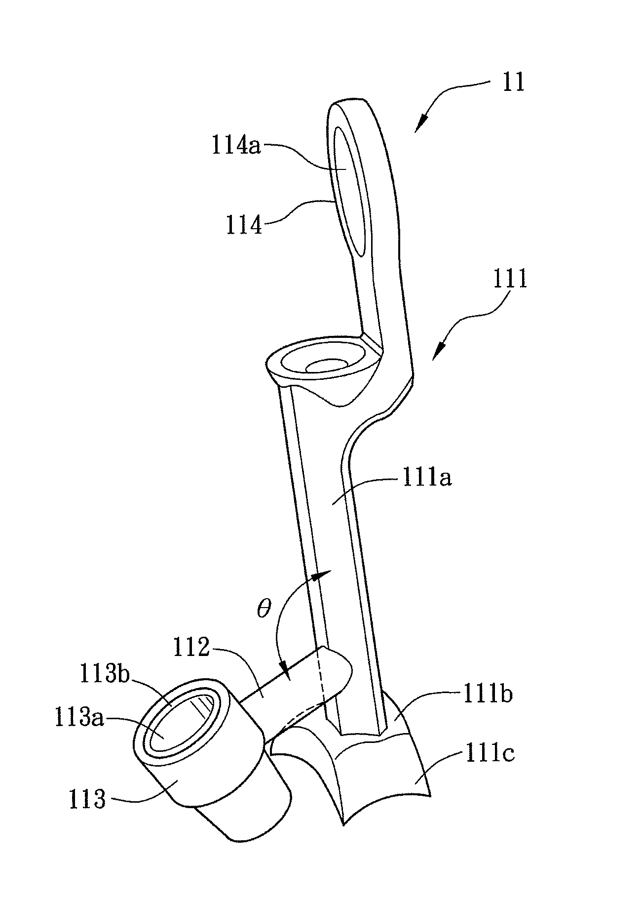
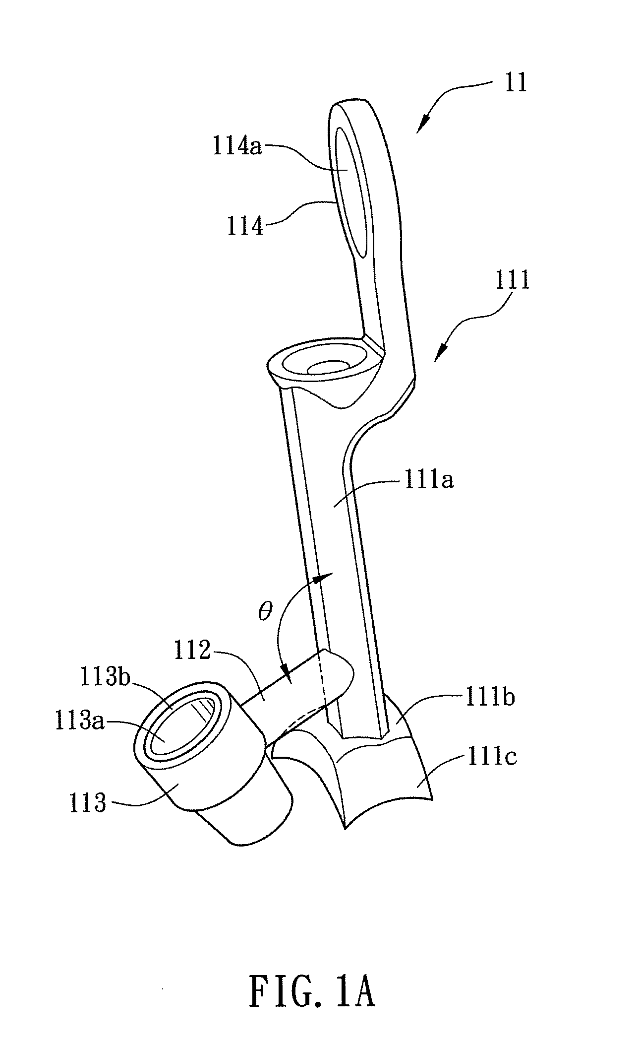
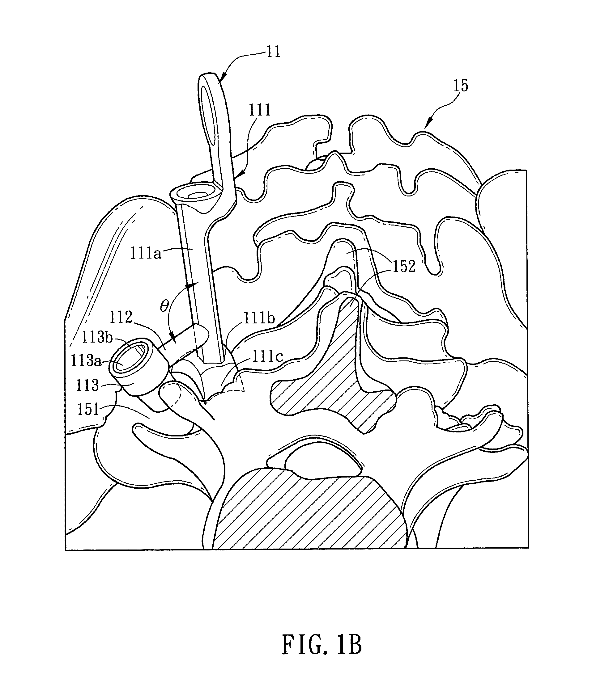
[0046]FIGS. 1A to 1E are schematic diagrams showing different elements of a guiding assembly for spinal drilling operation according to a preferred embodiment of the present invention. Referring to FIGS. 1A to 1E, a guiding assembly for spinal drilling operation includes a guiding element 11, an auxiliary element 12, a k-pin 13, and a cannular driller 14. The structural features of these elements will be described hereinafter.

[0047]With reference to FIG. 1A, the guiding element 11 includes a main body 111, a connection part 112, and a locating part 113.

[0048]The main body 111 has at least one stand portion 111a and at least one contact portion 111b. The stand portion 111a is mostly a vertical column, and the bottom thereof connects to the contact portion 111b. The main body 111 furthe...


PUM


Abstract

A method for spinal drilling operation is disclosed. The method includes the steps of disposing a guiding element on a vertebra; mounting an auxiliary element on a locating part of the guiding element; mounting a k-pin on the auxiliary element; locating the k-pin and removing the auxiliary element from the locating part; mounting a cannular driller having a holding part and a drilling part through the k-pin; and rotating the holding part to drive the drilling part for a reaming process. A guiding assembly for spinal drilling operation is also disclosed. Accordingly, the spinal drilling process can be conducted easier and more precisely.

Description

CROSS REFERENCE TO RELATED APPLICATIONS[0001]This Non-provisional application claims priority under 35 U.S.C. §119(a) on Patent Application No(s). 100110288 filed in Taiwan, Republic of China on Mar. 25, 2011, and Application No(s). 101108536 filed in Taiwan, Republic of China on Mar. 13, 2012, the entire contents of which are hereby incorporated by reference.BACKGROUND OF THE INVENTION[0002]1. Field of Invention[0003]The present invention relates to a method and a guiding assembly for drilling operation, and in particular, to a method and a guiding assembly for spinal drilling operation.[0004]2. Related Art[0005]Spine is such an important element in human body because it not only constructs the main frame of skeleton but has the function of protecting the inside spinal cord, which is the spindle of human nerve system. The nerves protrude outwardly from the inside of the vertebrae, and then extend forwardly, laterally, and vertically to the visceral organs as well as the extremity o...

Claims


Application Information

Patent Timeline
IPC IPC(8): A61B17/17A61B17/16
CPCA61B17/1671A61B2017/568A61B17/1757
Inventor FANG, JING-JINGLIN, RUEY-MOWU, IZU-CHIEHHOU, CHENG-YU
Owner NAT CHENG KUNG UNIV
Why Eureka
Try Eureka