
Apparatus and method for efficient dc-to-dc conversion through wide voltage swings

Active Publication Date: 2012-09-27
LEDILLION TECH
View PDF4 Cites 13 Cited by
  • Summary
  • Abstract
  • Description
  • Claims
  • Application Information

AI Technical Summary

Benefits of technology

[0011]The disclosed DC-to-DC converter has ultra high efficiency from reduced switching losses that enables very high switching frequency and reduced component sizes and weights. In addition, the converter has small magnetic components. Further, the converter provides high output DC load current capability.
[0012]The disclosed techniques reduce switching duty cycle variation to yield improved efficiency. Duty cycle variations are used to implement a range of voltage or current ratios. As duty cycles change to accommodate different transfer ratios, switch loss can increase due to the effect of parasitic capacitances and / or switch transition loss. The invention utilizes one or more switches as a switching mode changer. This reduces the need for dramatic changes in switching duty cycles, while still achieving a large voltage or current transfer ratio.

Problems solved by technology

For example, increasing switching frequency usually results in a reduction of component size, but concomitantly increase switching losses due to parasitic capacitances and switch transition losses.
As a result overall efficiency is reduced.
An AC source usually goes through a wide range of momentary voltages in each cycle, hindering any attempt to optimize a DC-to-DC converter for a specific input to output voltage ratio.
There are two disadvantages associated with this method.
First, a relatively large capacitor is required to store enough energy through a transition period.
Second, during transition periods small or no current is drained from the input, which results in electrical current drain from the input AC line to transpire over a narrower time frame, mostly around peak input voltages.
This eventually results in inefficient power transfer and a lower Power Factor.

Method used


Image

  • Apparatus and method for efficient dc-to-dc conversion through wide voltage swings
  • Apparatus and method for efficient dc-to-dc conversion through wide voltage swings
  • Apparatus and method for efficient dc-to-dc conversion through wide voltage swings

Examples


Embodiment Construction

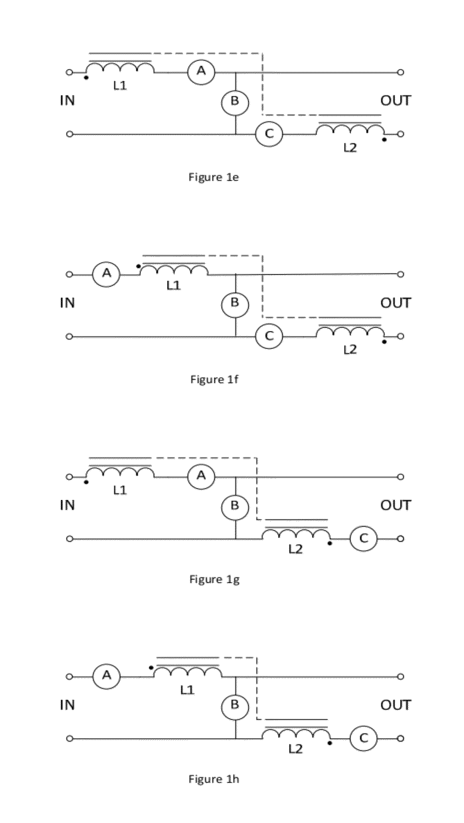
[0024]FIGS. 1a-1j illustrate various embodiments of a three-switch implementation of the invention. Observe that switch A is always in the input pathway and switch C is always in the output pathway. Depending upon the status of switch B and / or switch C, inductor energy storage can be through L1 only, or L1 and L2 in series.

[0025]In FIG. 1a, switch A can be a master toggling switch to achieve a step down (buck) conversion. The state of switch B is the inverse of the state of switch A. Switch C is always on. For example, when switch A is closed switch B is open so whenever input voltage is higher than output voltage a positive current passes through L1, switch A, Switch C and L2 to the output. Opening switch A and closing switch B disconnects the input. Consequently, stored energy in inductor L2 releases to output through switch C and switch B.

[0026]This configuration is in contrast to a buck converter where inductor energy storage and release pathways use both L1 and L2. In FIG. 1a i...


PUM


Abstract

A DC-to-DC converter includes two or more inductors coupled to a common core and two or more active switches, where at least one active switch is in an input current path. A controller operates the two or more active switches such that a DC input is driven through one or more of the two or more inductors to implement a power conversion operation.

Description

FIELD OF THE INVENTION[0001]This invention relates generally to power conversion. More particularly, this invention relates to an efficient DC-to-DC converter operable through wide voltage swings.BACKGROUND OF THE INVENTION[0002]There is a growing demand for DC-to-DC converters with improved conversion efficiency and reduced size. Design techniques vary, with some techniques reducing the voltage or current, others increasing the voltage or current, and still others alternately increasing or decreasing voltage or current. In a typical DC-to-DC converter, one or more switches connect to input power, a capacitor or inductor stores excess energy in one phase, and in another phase the stored energy is released to output nodes.[0003]Each technique has its own advantages and disadvantages. There are multiple tradeoffs between component sizes, overall efficiency and optimal zones of input to output voltage ratios. For example, increasing switching frequency usually results in a reduction of...

Claims


Application Information

Patent Timeline
IPC IPC(8): H02M3/335
CPCH02M2003/1557H02M3/335H02M3/158H02M3/33569H02M3/1557
Inventor KASSAYAN, REZA
Owner LEDILLION TECH
Learn More