Leakage Power Management Using Programmable Power Gating Transistors and On-Chip Aging and Temperature Tracking Circuit

a technology of aging and temperature tracking circuits, applied in the direction of power consumption reduction, electronic switching, pulse technique, etc., can solve the problems of reducing the possible power savings of the integrated circuit operating at lower temperatures, affecting the accuracy of aging detection, and requiring the corresponding gating transistor size, so as to eliminate the effect of process-induced variations and simplify the aging process

Active Publication Date: 2012-09-27
WISCONSIN ALUMNI RES FOUND
View PDF4 Cites 12 Cited by
  • Summary
  • Abstract
  • Description
  • Claims
  • Application Information

AI Technical Summary

Benefits of technology

[0006]First, the power gating transistors must be sized to accommodate high leakage currents when the circuit is at high operating temperatures. Because such power gating transistors approximate constant current sources, as the temperature of the integrated circuit drops and leakage current would be expected to decrease, the constant current operation of the power gating transistors increases the voltage on the integrated circuit, undoing some of the expected drop in leakage current, and thereby decreasing the possible power savings when the integrated circuit is operating at lower temperatures.
[0042]It is thus a feature of at least one embodiment of the invention to provide a simple method of quantifying a temperature signal for control of the power gating transistors.

Problems solved by technology

First, the power gating transistors must be sized to accommodate high leakage currents when the circuit is at high operating temperatures.
Because such power gating transistors approximate constant current sources, as the temperature of the integrated circuit drops and leakage current would be expected to decrease, the constant current operation of the power gating transistors increases the voltage on the integrated circuit, undoing some of the expected drop in leakage current, and thereby decreasing the possible power savings when the integrated circuit is operating at lower temperatures.
Second, the power gating transistors must be sized to accommodate their decreased current output over time (as a result of negative bias temperature instability).
As a result, the integrated circuit operates at higher voltages than necessary during the first few years of operation with a corresponding increase in current leakage of the controlled circuitry.

Method used


Image

  • Leakage Power Management Using Programmable Power Gating Transistors and On-Chip Aging and Temperature Tracking Circuit
  • Leakage Power Management Using Programmable Power Gating Transistors and On-Chip Aging and Temperature Tracking Circuit
  • Leakage Power Management Using Programmable Power Gating Transistors and On-Chip Aging and Temperature Tracking Circuit

Examples


Embodiment Construction

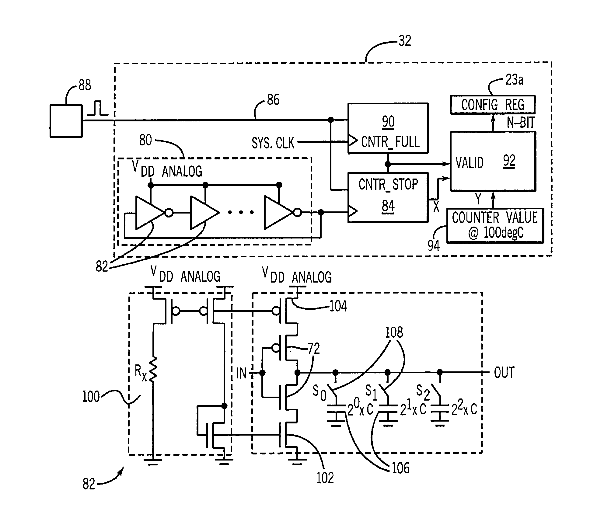
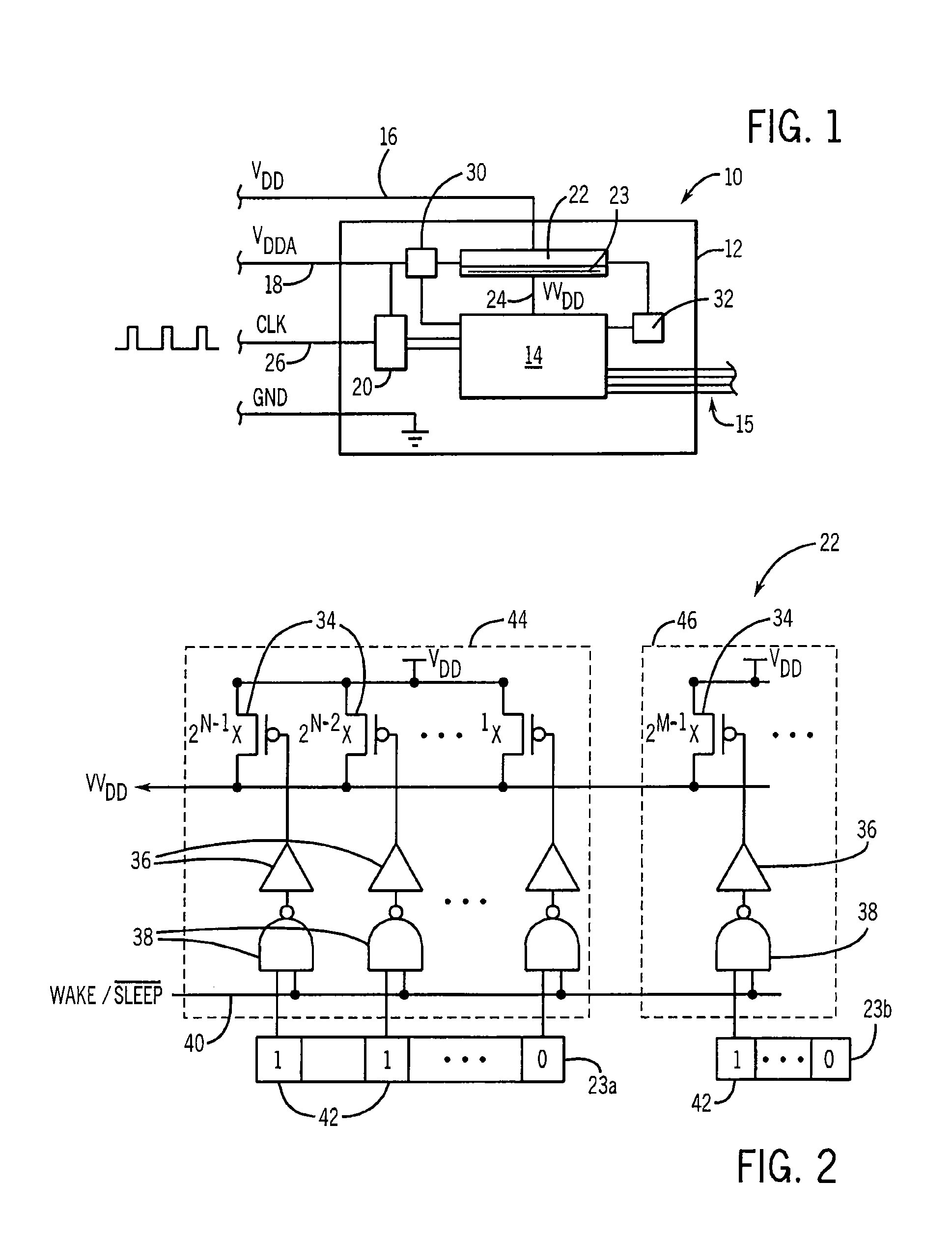
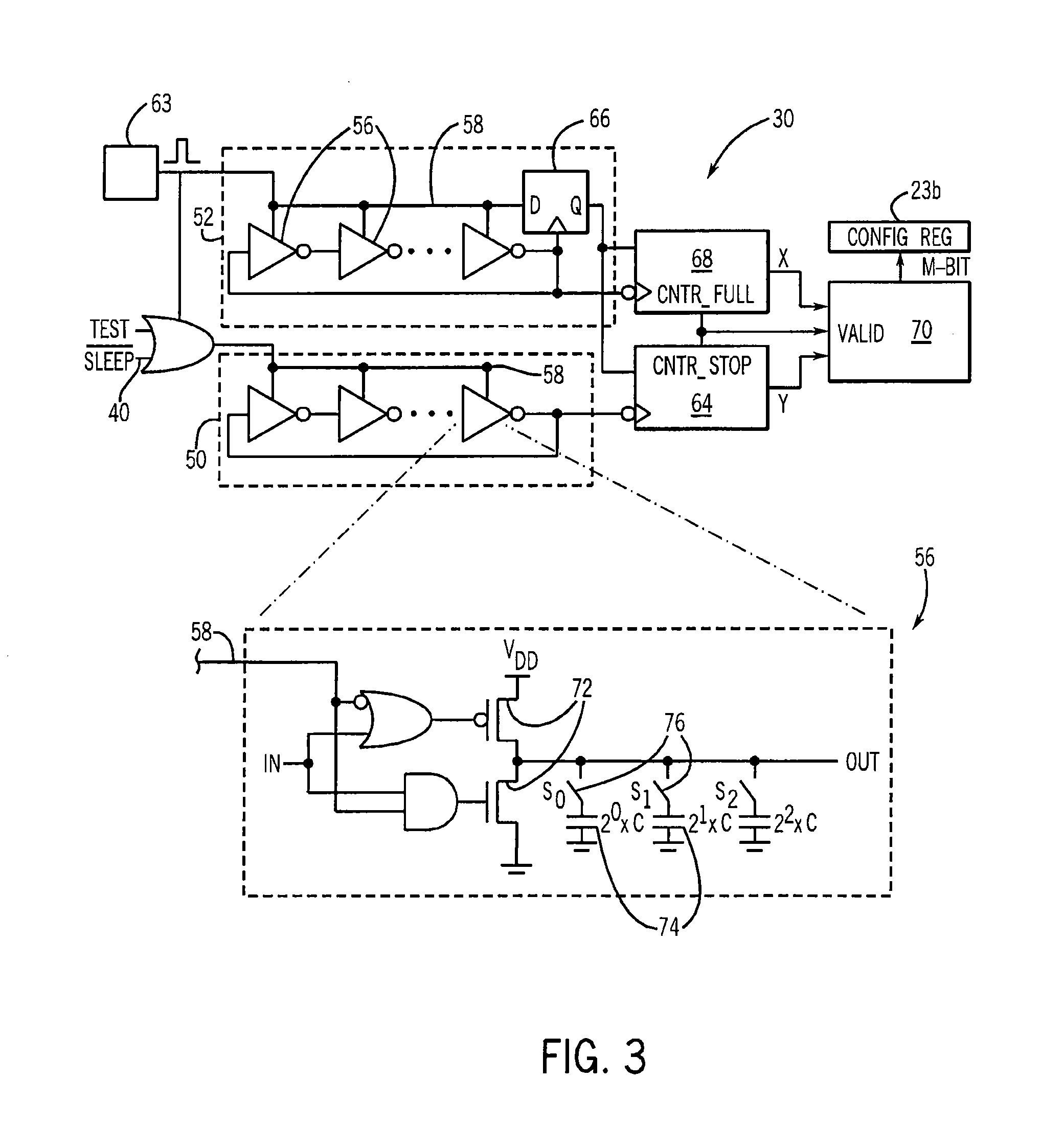
[0050]Referring now to FIG. 1, an integrated circuit 10 may provide a substrate 12 having application circuitry 14 implementing the primary function of the integrated circuit 10. The application circuitry 14 may be, for example, microprocessor circuitry, digital signal processing circuitry, FPGA circuitry and the like and typically communicates with other devices and components via one or more input / output lines 15. The application circuitry 14 may be constructed on the substrate 12 according to standard lithography techniques and include components such as resistors, capacitors, and transistors including but not limited to PMOS and NMOS type transistor devices.

[0051]The integrated circuit 10 may receive external power supplies 16 (VDD) and 18 (VDDA). The power supply 16 may provide, for example, power to the application circuitry 14 while the power supply 18 may provide an analog reference voltage, for example, to a phase lock loop 20 used to synthesize clock signals on the integra...


PUM


Abstract

The number of power-gating transistors on an integrated circuit used for power reduction in a sleep mode is controlled during a wake state to adjust the current flow and hence voltage drop across the power-gating transistors as a function of aging of these transistors and / or a function of temperature of the integrated circuit. In this way, the supply voltage to the integrated circuit may be better tailored to minimize current leakage when the integrated circuit is young or operating at low temperatures.

Description

BACKGROUND OF THE INVENTION[0001]The present invention relates to architectures for integrated circuits and in particular to a method and apparatus for managing transistor leakage currents in high-density integrated circuits such as microprocessors and the like.[0002]Managing the power consumption of integrated circuits such as microprocessors is important for the purposes of energy conservation, providing improved battery life for portable devices, and reducing problems of device cooling.[0003]One method of reducing power consumption is to place the integrated circuit in a “sleep state” when its full capabilities are not required. The sleep state may be implemented through a set of power gating transistors placed between the input power terminal (VDD) of the integrated circuit and an effective power terminal (VVDD) of the of the integrated circuitry that will be shut down to conserve power. A sleep / wake signal (generated externally or internally) turns these power gating transistor...

Claims


Application Information

Patent Timeline
IPC IPC(8): H03K17/14H03K17/56
CPCH03K19/0016
Inventor KIM, NAM SUNG
Owner WISCONSIN ALUMNI RES FOUND
Why Eureka
Try Eureka