
Magnetic resonance method and system to detect interference signals in magnetic resonance spectroscopy signals

a magnetic resonance spectroscopy and interference signal technology, applied in the field of magnetic resonance method and system to detect interference signals in magnetic resonance spectroscopy signals, can solve the problems of non-optimal residual, interference signals occur, and hinder the signal evaluation of usable signals, so as to reduce labor costs and achieve reliable results

Inactive Publication Date: 2012-09-20
SIEMENS AG
View PDF3 Cites 7 Cited by
  • Summary
  • Abstract
  • Description
  • Claims
  • Application Information

AI Technical Summary

Benefits of technology

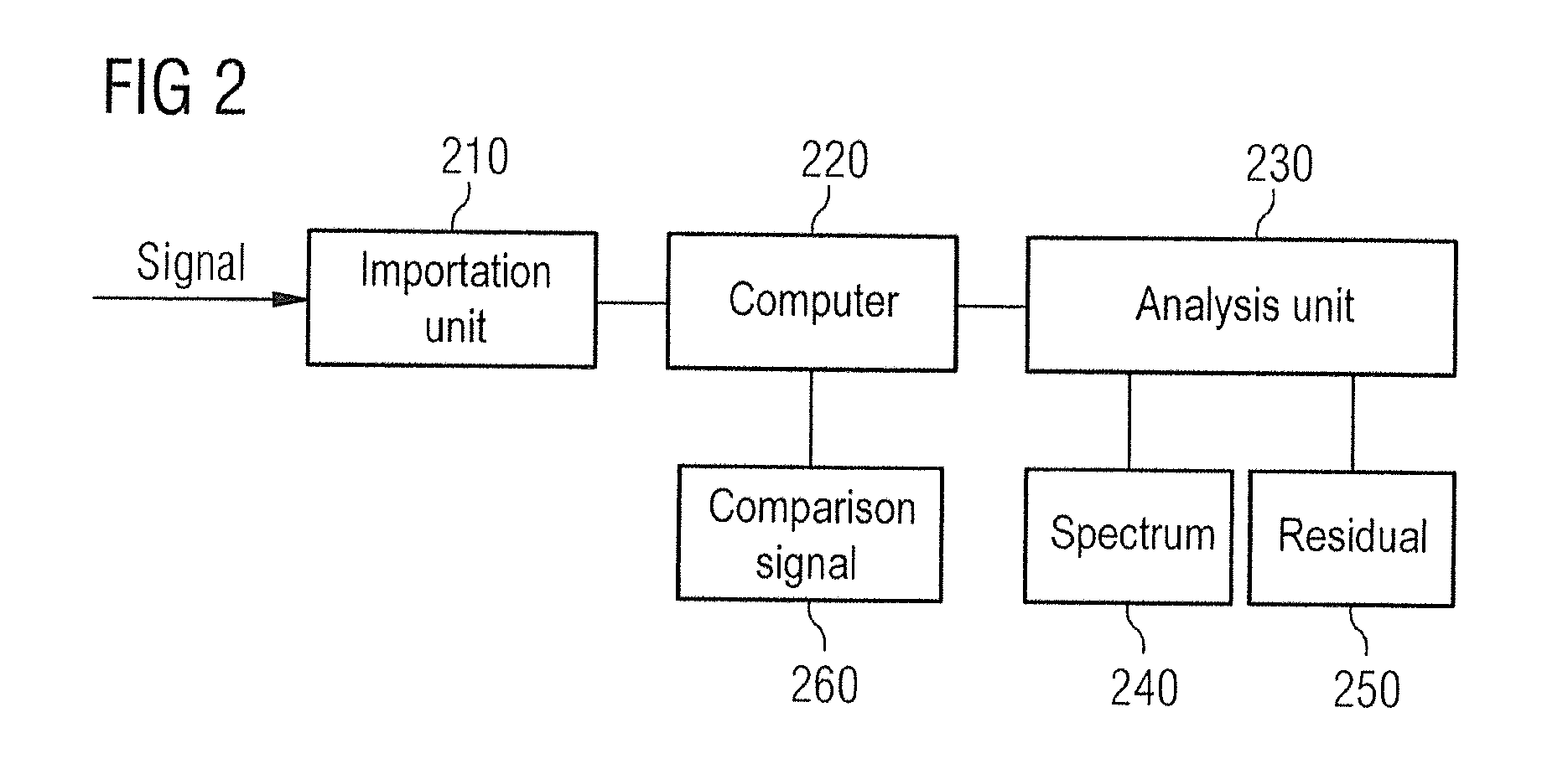
[0010]A comparison signal is reconstructed, i.e. a comparison signal is generated computationally that, for example, is formed as a sum of exponential functions and recreates the measured magnetic resonance spectroscopy signal as well as possible. In particular, the corresponding mathematical representation of the comparison signal by a frequency representation allows a simple determination of characteristic resonance lines of the examined substances. The magnetic resonance spectroscopy signal and the comparison signal can be presented and processed either in the time domain or in the frequency domain.
[0023]The present invention therefore offers the advantage that interference signals in which no or little usable signals are analyzed and presented directly in a spectrum representation of the residual, such that the interfere signals are significantly more unambiguously recognizable than in the acquired spectrum of the measured magnetic resonance spectroscopy signal.
[0024]Furthermore, via the presentation and analysis of the interference signals in a measured magnetic resonance spectroscopy signal the present invention allows a decision as to whether this is suitable for a further evaluation or not. For example, via the present invention the quality of the magnetic resonance spectroscopy signals can be checked automatically by software. Spectra in which interference signals are detected in the form of spikes would thus be marked as poor and be removed from further handling and the results presentation. More reliable results can be obtained in this manner, and the labor cost to create a finding can be reduced. Software in accordance with the invention for automatic testing of the quality of magnetic resonance spectroscopy signals can be integrated into software of a device for imaging magnetic resonance tomography, or into a corresponding software for post-processing of such signals.

Problems solved by technology

These interference signals occur due to non-optimal residual magnetization suppression, for example, during the spectroscopic signal acquisition.
These interference signals can hinder the signal evaluation of the usable signal because such spikes could be erroneously perceived as resonance lines of the usable signal, and such spikes may overlay the resonance lines of the usable signal so that they are not distinctly recognizable as interference signals but severely adulterate the usable signal.
These spikes can therefore impede or make impossible an evaluation of the acquired spectra.
Persons with less experience in the data evaluation of magnetic resonance spectra are therefore incapable of sufficiently assessing and interpreting the data.

Method used


Image

  • Magnetic resonance method and system to detect interference signals in magnetic resonance spectroscopy signals
  • Magnetic resonance method and system to detect interference signals in magnetic resonance spectroscopy signals
  • Magnetic resonance method and system to detect interference signals in magnetic resonance spectroscopy signals

Examples


Embodiment Construction

[0030]FIG. 1 schematically illustrates a magnetic resonance system 5 that can be used both for imaging magnetic resonance tomography and for magnetic resonance spectroscopy. A basic magnetic field magnetic 1 generates a temporally constant, strong magnetic field for polarization or alignment of the nuclear spins in an examination region of a subject O, for example of a portion of a human body that is to be examined. This subject O, situated on a table 23, is moved into the magnetic resonance system 5 for data acquisition. The high homogeneity of the basic magnetic field that is required for the magnetic resonance measurement (data acquisition) is defined in a measurement volume M. Shim plates made of ferromagnetic material are mounted at a suitable point to assist the homogeneity requirements, in particular to eliminate temporally invariable influences. Temporally variable influences are eliminated by shim coils 2 supplied with signals from a shim coil supply 23.

[0031]A cylindrical ...


PUM


Abstract

In a method and device to detect interference signals in magnetic resonance spectroscopy signals a comparison signal is computationally reconstructed that optimally approximates a measured, detected magnetic resonance spectroscopy signal. The comparison signal forms spectral components of resonance lines of the measured magnetic resonance spectroscopy signal. A residual is calculated from the difference of the two signals (comparison signal and magnetic resonance spectroscopy signal) in the frequency representation. The interference signals are determined from the residual.

Description

BACKGROUND OF THE INVENTION[0001]1. Field of the Invention[0002]The present invention concerns a method and system in order to detect interference signals that occur in the form of spikes in the frequency representation of magnetic resonance spectroscopy signals.[0003]2. Description of the Prior Art[0004]In magnetic resonance spectroscopy signals, unwanted interference signals are sometimes present that are recognizable in the form of spikes in the frequency representation of the spectroscopy signal. These interference signals occur due to non-optimal residual magnetization suppression, for example, during the spectroscopic signal acquisition.[0005]These interference signals can hinder the signal evaluation of the usable signal because such spikes could be erroneously perceived as resonance lines of the usable signal, and such spikes may overlay the resonance lines of the usable signal so that they are not distinctly recognizable as interference signals but severely adulterate the u...

Claims


Application Information

Patent Timeline
IPC IPC(8): G01R33/44
CPCG01R33/4625G01R33/565G01R33/485
Inventor WEILAND, ELISABETH
Owner SIEMENS AG
Learn More