Gravity drainage startup using RF & solvent

a gravity drainage and solvent technology, applied in the direction of fluid removal, earthwork drilling and mining, borehole/well accessories, etc., can solve the problems of large steam generation cost, many sites are not amendable, and the use of water for heavy oil production can be technically challenging, so as to speed up the thermal communication, improve the start up efficiency of the sagd, and increase the pressure

Active Publication Date: 2012-09-20
HARRIS CORP +1
View PDF31 Cites 21 Cited by
  • Summary
  • Abstract
  • Description
  • Claims
  • Application Information

AI Technical Summary

Benefits of technology

[0018]Generally speaking, the invention is a method of improving the start up efficiency of an SAGD or other steam assisted hydrocarbon production process by soaking a wellbore in solvent and vaporizing that solvent with RF energy. The vaporized solve...

Problems solved by technology

There are extensive deposits of viscous hydrocarbons throughout the globe, including large deposits in the Northern Alberta tar sands, which are not recoverable with traditional oil well production technologies because the hydrocarbons are too viscous to flow.
However, many sites are not amendable to open-pit mining techniques.
Due to costs and environmental concerns, the use of water for the production of heavy oil can be technically challenging.
Furthermore, as in all thermal recovery processes, the cost of steam generation is a major part of the cost of oil production.
Historically, ...

Method used


Image

  • Gravity drainage startup using RF & solvent
  • Gravity drainage startup using RF & solvent
  • Gravity drainage startup using RF & solvent

Examples


Embodiment Construction

[0028]Turning now to the detailed description of the preferred arrangement or arrangements of the present invention, it should be understood that the inventive features and concepts may be manifested in other arrangements and that the scope of the invention is not limited to the embodiments described or illustrated. The scope of the invention is intended only to be limited by the scope of the claims that follow.

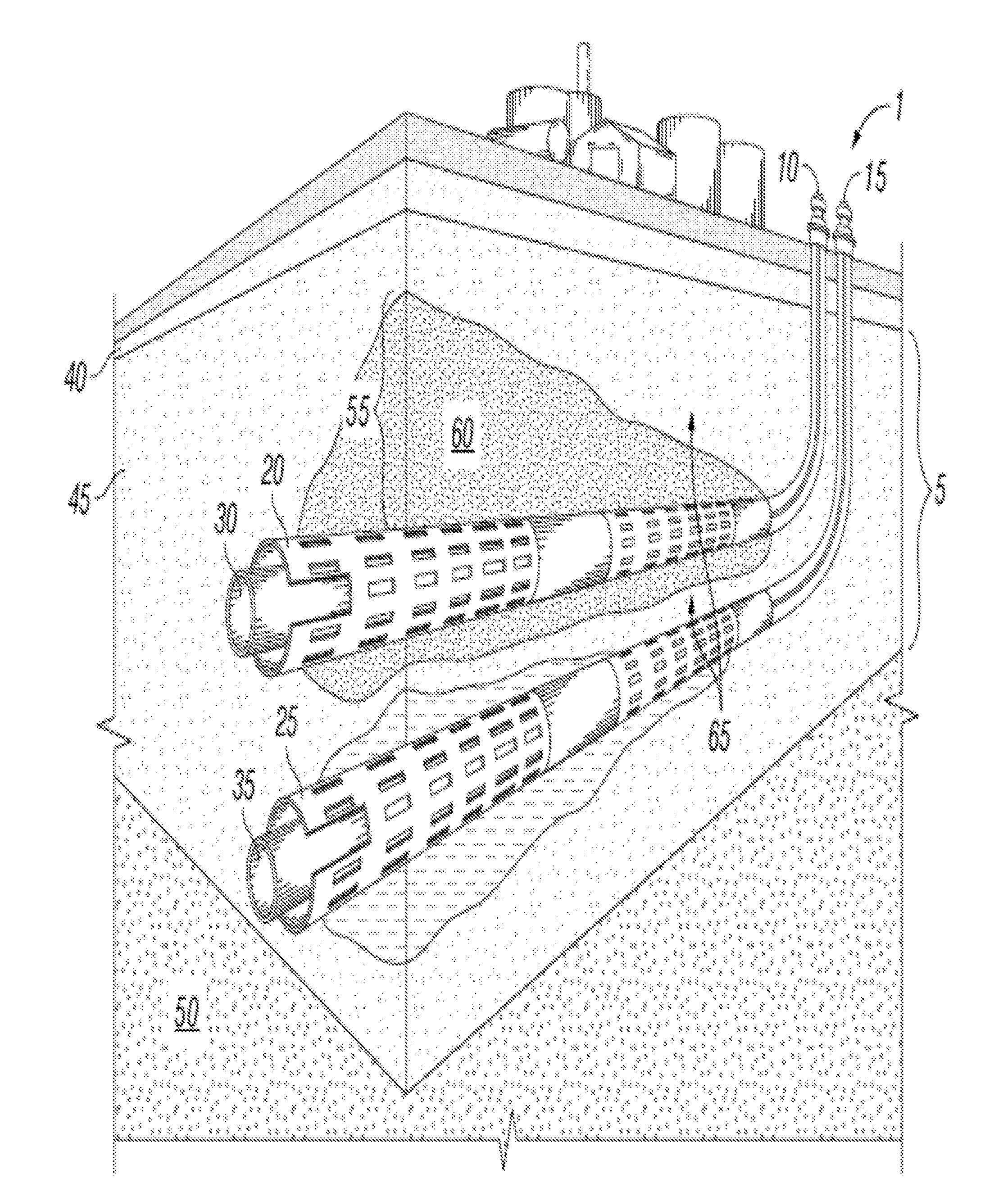
[0029]A well pair for a gravity drainage operation is shown in FIG. 1. As shown in FIG. 1, the gravity drainage operation well pair 1 is drilled into a formation 5 with one of the wells vertically spaced proximate to the other well. The injection well 10 is an upper, horizontal well, and the production well 15 is a lower, parallel, horizontal well vertically spaced proximate to the injection well 10.

[0030]In an alternate embodiment, the injection well 10 is vertically spaced about 4 to 10 meters above the production well 15. In yet another embodiment, the injection well 10 is...


PUM


Abstract

The method begins by forming a gravity drainage production well pair within a formation comprising an injection well and a production well. The pre-soaking stage begins by soaking at least one of the wellbores of the well pair with a solvent, wherein the solvent does not include water. The pre-heating stage begins by heating the soaked wellbore of the well pair to produce a vapor. The squeezing stage begins by introducing the vapor into the soaked wellbore of the well pair, and can thus overlap with the pre-heating stage. The gravity drainage production begins after the squeezing stage, once the wells are in thermal communication and the heavy oil can drain to the lower well.

Description

CROSS-REFERENCE TO RELATED APPLICATIONS[0001]This application claims priority to U.S. Provisional 61 / 382,675, filed Sep. 14, 2010, and 61 / 411,333, filed Nov. 8, 2010, each of which is incorporated herein in its entirety.STATEMENT REGARDING FEDERALLY SPONSORED RESEARCH[0002]None.FIELD OF THE INVENTION[0003]A method of operating a gravity drainage operation for enhanced oil recovery.BACKGROUND OF THE INVENTION[0004]There are extensive deposits of viscous hydrocarbons throughout the globe, including large deposits in the Northern Alberta tar sands, which are not recoverable with traditional oil well production technologies because the hydrocarbons are too viscous to flow. Indeed, the viscosity can be as high as one million centipoise. In some cases, these deposits are mined using open-pit mining techniques to extract the hydrocarbon-bearing material for later processing to extract the hydrocarbons. However, many sites are not amendable to open-pit mining techniques.[0005]As an alternat...

Claims


Application Information

Patent Timeline
IPC IPC(8): E21B43/24
CPCE21B43/2408
Inventor SULTENFUSS, DANIEL R.DREHER, JR., WAYNE REIDWHEELER, JR., THOMAS J.PARSCHE, FRANCIS E.TRAUTMAN, MARK A.
Owner HARRIS CORP
Why Eureka
Try Eureka