Dye-sensitized solar cell

a solar cell and dye-sensitive technology, applied in the field of dye-sensitive solar cells, can solve the problems of high production cost and large installation area of large-area cells, and achieve the effects of no deterioration, stable utilization, and reduced thermal stress caused by the difference between expansion and shrinkag

Inactive Publication Date: 2012-09-20
USHIO DENKI KK
View PDF2 Cites 4 Cited by
  • Summary
  • Abstract
  • Description
  • Claims
  • Application Information

AI Technical Summary

Benefits of technology

[0020]Then, according to the present invention, thermal stresses caused by the difference of the expansion and the shrinkage can be diminished because of the configuration wherein a buffer glass is present as an intermediate layer between the small diameter lead part of the counter electrode and the glass of the tube-shaped vessel, there is no risk even in case of a rod-shaped counter electrode that breakages such as cracks are generated in the sealing portion during the cooling process after the sealing.
[0021]Because the sealing portions are formed from glass, there is no deterioration despite the irradiation with UV rays contained in the sunlight, and a stable utilization for a long period becomes possible.

Problems solved by technology

However, from the viewpoint of manufacture, there are the problems that conditions of a high temperature and a high vacuum are necessary, so that it is difficult to implement large area cells, and the production costs are high.

Method used


Image

  • Dye-sensitized solar cell
  • Dye-sensitized solar cell
  • Dye-sensitized solar cell

Examples


Embodiment Construction

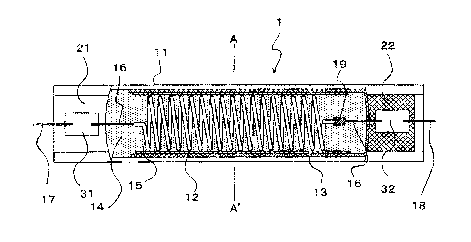
[0027]FIG. 1(a) shows a cross-sectional view of a dye-sensitized solar cell according to an embodiment of the present invention along the direction of the tube axis, FIG. 1(b) shows a cross-sectional view of a state wherein only the sealing portion of FIG. 1(a) has been rotated for 90°, and FIG. 1(c) shows a cross-sectional view of A-A′ in FIG. 1(a) along the direction of the tube diameter.

[0028]At the inner surface of a tube-shaped vessel 11, a transparent conductive film 12 and a photoelectrode 13 being formed on this transparent conductive film 12 are provided sequentially. In the interior of the tube-shaped vessel 11, a coil shaped counter electrode 15 is arranged along the longitudinal direction. Both ends of the tube-shaped vessel 11 are sealed, and an electrolytic solution 14 is enclosed with the interior thereof.

[0029]Below, each structure will be explained concretely. In the following explanation, the right end part in the drawing will be referred to as ‘the one end part’ w...


PUM


Abstract

A dye-sensitized solar cell having a transparent conductive film at the inner surface of a tube-shaped transparent glass vessel, a semiconductor film photoelectrode to which a dye has been adsorbed formed on this transparent conductive film, and a counter electrode provided in the tube-shaped vessel spaced from this photoelectrode and an electrolytic solution enclosed in the tube-shaped vessel. Both ends of the tube-shaped vessel are tightly sealed by formation of sealing portions melting and compress the glass of the vessel; the transparent conductive film extends into the sealing portion at one end of the tube and an external lead is connected electrically to said transparent conductive film and is led out from the sealing portion to the outside of the tube-shaped vessel; and a lead connected electrically to the counter electrode is led out from the sealing portion at the other end to the outside of the tube-shaped vessel.

Description

BACKGROUND OF THE INVENTION[0001]1. Field of the Invention[0002]This invention relates to dye-sensitized solar cells. In particular, it relates to dye-sensitized solar cells having a light-permeable tube-shaped vessel.[0003]2. Description of Related Art[0004]Heretofore, development of solar cells as new energy sources with less influence on the global environment has been performed. Solar cells utilizing silicon semiconductors have a high conversion rate and an excellent light stability and therefore are generally widely used. However, from the viewpoint of manufacture, there are the problems that conditions of a high temperature and a high vacuum are necessary, so that it is difficult to implement large area cells, and the production costs are high.[0005]Dye-sensitized solar cells wherein an electrolytic solution is filled into the interior of a transparent vessel, a photoelectrode of a porous semiconductor to which a dye has been adsorbed, and a counter electrode are provided, and...

Claims


Application Information

Patent Timeline
Patent Type & Authority Applications(United States)
IPC IPC(8): H01L31/0224
CPCH01G9/2031H01G9/2059Y02E10/542H01G9/2086H01G9/2077Y02E60/10H01L31/04H01M14/00H01M50/531H01M50/543
Inventor NAKAMURA, MASAKI
Owner USHIO DENKI KK
Why Eureka
Try Eureka