
Multiple projectile ammunition

Inactive Publication Date: 2012-09-20
CARMEL MATTHEW MORMAN
View PDF7 Cites 10 Cited by
  • Summary
  • Abstract
  • Description
  • Claims
  • Application Information

AI Technical Summary

Benefits of technology

[0005]Embodiments of the present invention overcome certain shortcomings of conventional cartridges and fulfill previously unmet commercial cartridge offerings. More specifically, embodiments of the present invention relate to a cartridge including a plurality of stacked projectiles. Advantageously, this cartridge is configured in a manner whereby the projectiles reliably separate and tumble upon entering a target (e.g., tissue of a person). The underlying benefit is that, for a short-barreled handgun, a cartridge configured in accordance with an embodiment of the present invention provides similar energy transfer and physiological effect to a fully expanded HP bullet but at a lower velocity and felt recoil.

Problems solved by technology

However, this round of ammunition is also known to not be well suited for handguns with relatively short barrels (e.g., 2″-3″ barrels).
This is a result of the relatively short barrel length typically not generating sufficient velocity to ensure reliable bullet expansion (i.e., obturation).
In addition, the high recoil force associated with this round can hinder accurate shooting and / or cause discomfort in the hand of some shooter's.
This presents a problem for some shooters with limited hand strength or manual dexterity issues who have a desire to employ an effective self-defense cartridge using a controllable and comfortable firearm platform.
Furthermore, there are limited offerings of self-defense cartridges for short-barreled handguns.
More specifically, there currently are no commercially produced non-frangible cartridges designed specifically for point blank or close range engagement.
This void in commercially available non-frangible cartridges includes non-frangible cartridges that offer rapid and complete bullet expansion at the low velocities inherent in standard pressure loads when fired from short-barreled handguns.

Method used


Image

  • Multiple projectile ammunition
  • Multiple projectile ammunition

Examples


Embodiment Construction

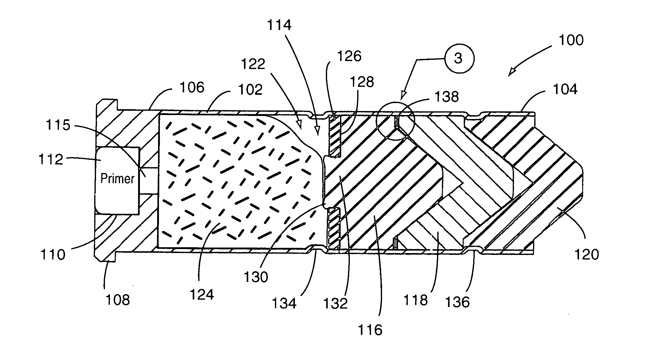
[0013]FIGS. 1 and 2 show a round of ammunition (e.g., a cartridge 100) configured in accordance with an embodiment of the present invention. The cartridge 100 includes a casing 102 having a projectile receiving end portion 104 and a primer receiving end portion 106. A rim 108 and a primer bore 110 are provided at the primer receiving end portion 106. The primer bore 110 is configured for having a primer 112 mounted therein. It is disclosed herein that a water-resistance seal can be provided between the primer 112 and the casing 102 by providing a suitable sealant between the primer 112 and a mating wall of the primer bore 110.

[0014]The casing 102 has a substantially round cross sectional shape. The projectile receiving end portion 104 defines an open end portion of the casing 102. The primer receiving end portion 106 defines a closed end portion of the casing 102 (i.e., when the primer 112 is within the primer bore 110. A casing cavity 114 is defined between the projectile receiving...


PUM


Abstract

A casing has a projectile receiving end portion and a primer receiving end portion. A plurality of projectiles is positioned in a stacked configuration within the casing at the projectile receiving end portion. A propellant receiving space is defined within the casing between an innermost one of the projectiles and the primer receiving end portion of the casing. The innermost one of the projectiles has a gas check body attached thereto at an end face thereof exposed to the propellant receiving space of the casing. A first cannulure is positioned between the gas check body and the primer receiving end portion of the casing for defining a protrusion for limiting displacement of the gas check body toward the primer receiving end portion of the casing. A second cannulure is positioned within the projectile receiving end portion of the casing for forming a protrusion that engages an outermost one of the projectiles.

Description

FIELD OF THE DISCLOSURE[0001]The disclosures made herein relate generally to ammunition for firearms and, more particularly, to firearm ammunition having a plurality of stacked projectiles.BACKGROUND[0002]The .38 Special +P / HP (i.e., enhanced pressure hollow point) cartridge is known to be one of the most popular self-defense rounds of ammunition. However, this round of ammunition is also known to not be well suited for handguns with relatively short barrels (e.g., 2″-3″ barrels). This is a result of the relatively short barrel length typically not generating sufficient velocity to ensure reliable bullet expansion (i.e., obturation). In addition, the high recoil force associated with this round can hinder accurate shooting and / or cause discomfort in the hand of some shooter's. This presents a problem for some shooters with limited hand strength or manual dexterity issues who have a desire to employ an effective self-defense cartridge using a controllable and comfortable firearm plat...

Claims


Application Information

Patent Timeline
IPC IPC(8): F42B5/03F42B14/00F42B30/02
CPCF42B30/02F42B5/03
Inventor CARMEL, MATTHEW MORMAN
Owner CARMEL MATTHEW MORMAN
Learn More