
Counter-Die For The Cylinders of Rotary Die Cutting Machines

a technology of rotary die cutting machine and counter die, which is applied in the direction of sawing equipment, stock shearing equipment, shearing equipment, etc., can solve the problems of high maintenance cost and liable to suffer dilation, and achieve the effect of preventing blade damag

Active Publication Date: 2012-09-20
ROTARY DIECUTTING MONTENEGRO
View PDF2 Cites 0 Cited by
  • Summary
  • Abstract
  • Description
  • Claims
  • Application Information

AI Technical Summary

Benefits of technology

"The invention is a counter-die or dolly used in rotary stamping machines to cover the cylinder and protect the blades of the die. The counter-die is designed to be easy and fast to install, with a long useful life and improved expulsion of residues. It is made up of a tubular body with two layers, one of which is rigid and stable. The counter-die is connected together with a connection system that allows for easy replacement and minimal downtime. The system is also designed to control dilation and movement of the units on the cylinder, resulting in improved stability and efficiency of the stamping process. The interior elements of the counter-die are reusable, reducing waste and environmental impact. Overall, the invention provides a better and more stable counter-die for protection and improved performance of the stamping process."

Problems solved by technology

The problem with dollies or counter-dies of this type is that they do not have good dimensional stability that would make it possible to maintain the circumferential diameter throughout the whole lifetime of the device, as its support lacks rigidity, making them liable to suffer dilation due to thermal effects.
Additionally it should be pointed out that devices of this type are difficult to implement, giving rise to high maintenance costs due to the long times machines have to be taken out of service so that they can be replaced.
Apart from the problem described above, it also has to be said that counter-dies do not usually fit the cylinder perfectly, making it possible for them to move in certain ways that are negative for the stamping process.

Method used


Image

  • Counter-Die For The Cylinders of Rotary Die Cutting Machines
  • Counter-Die For The Cylinders of Rotary Die Cutting Machines
  • Counter-Die For The Cylinders of Rotary Die Cutting Machines

Examples


Embodiment Construction

[0009]The counter-die proposed resolves the above problems in a fully satisfactory way, in all of the different aspects mentioned.

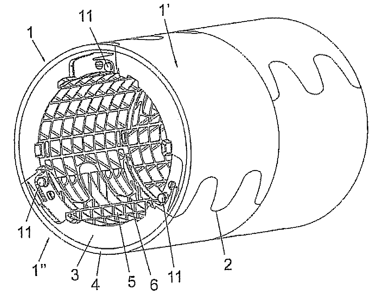
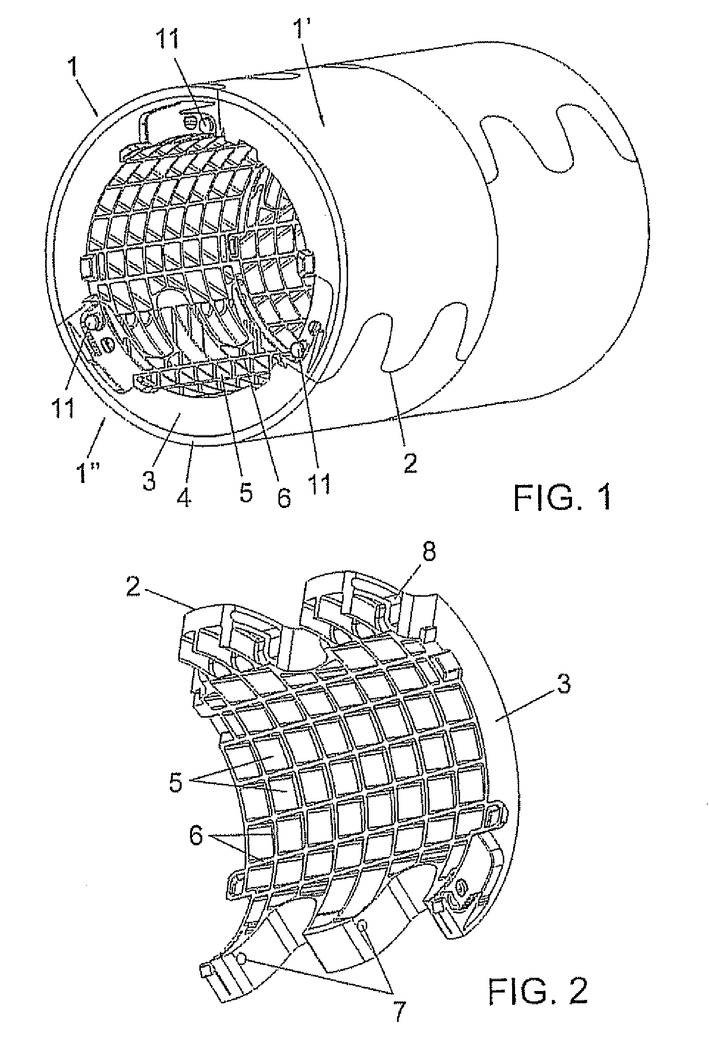
[0010]To this end and more specifically, the said counter-die takes the form of a tubular body, based on two layers, one thicker interior layer obtained using injected plastic, rigid, consistent and with very stable dimensions, and an exterior layer or coating based on vulcanized consumable polyurethane, which ensures any possible dilations that occur are minimum, as well as more regular and uniform.

[0011]The said set therefore offers maximum dimensional stability, making it possible to keep a uniform diameter of circumference throughout the whole useful life of the device.

[0012]According to another of the characteristics of the invention, the said tubular body that forms the counter-die is divided into a series of parts that may be fitted together circumferentially, preferentially three parts, including a connection system that makes the maneuver of repl...


PUM

PropertyMeasurementUnit
shapeaaaaaaaaaa
sizeaaaaaaaaaa
rigidityaaaaaaaaaa

Abstract

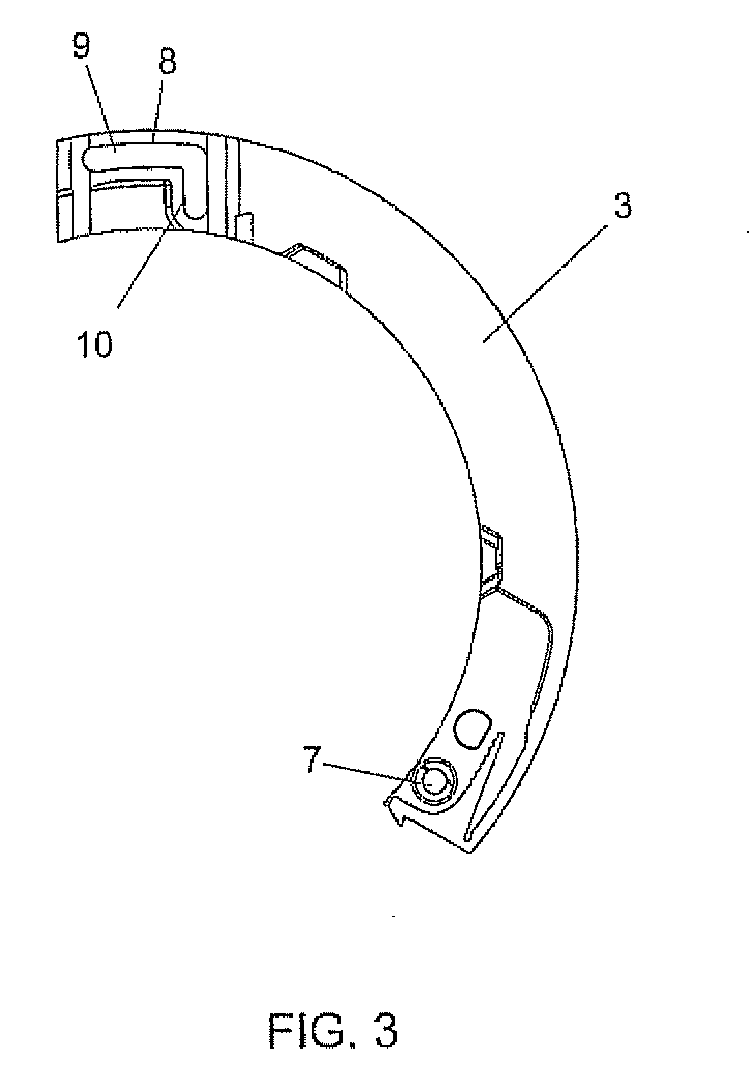
Specially designed to form an element that is easy and fast to install, with a long useful life and which improves the expulsion of residues after stamping, the counter-die of the invention is composed of a tubular body, divided into several parts (1-1′-1″) and joined to each other by tongue and groove joints using twisted edges (2) at the ends, preferentially three parts, these having an inner sector (3) which is the largest, of injected plastic, very resistant and light, over the exterior surface of which there is a coating (4) of polyurethane. The parts are joined to each other by orifices and grooves in their ends, more specifically in the area made of injected plastic, through which the respective rods or pins (11) pass.

Description

OBJECT OF THE INVENTION[0001]This invention refers to a counter-die or dolly, that is, an element which is used to cover the cylinder on which the die acts, with the aim of preventing damage to the blades of the latter.[0002]The object of the invention is to attain a counter-die that is easy and fast to fit onto the cylinder, with a long useful life and which improves the expulsion of residues after stamping, as well as a series of additional advantages that will be described throughout this document.BACKGROUND OF THE INVENTION[0003]As it is known, in rotary stamping machines two cylinders work, between which the piece to be stamped is placed, while one of the cylinders includes the blades of the die itself, while the other functions as the stamping base.[0004]This cylinder that works as the base for stamping is made of steel, and to ensure that the blades of the die are not damaged during stamping, it is equipped with a dolly made of a relatively soft material, usually polyurethane...

Claims


Application Information

Patent Timeline
Patent Type & Authority Applications(United States)
IPC IPC(8): B26D1/20
CPCB26D7/20B26D7/204B26F1/384Y10T83/4841Y10T83/9312Y10T83/7863
Inventor BENGOA RODRIGUEZ, ELIAS ADOLFO
Owner ROTARY DIECUTTING MONTENEGRO
Learn More