
Honing apparatus

a honing apparatus and guide member technology, applied in the field of honing apparatus, can solve the problems of reducing the processing accuracy of the cylinder bore, increasing the operating cost, and affecting the operation efficiency so as to minimize the abrasion of the guide member, the operating cost of the honing apparatus can be reduced, and the effect of reducing the operating cos

Inactive Publication Date: 2012-09-13
SUBARU CORP
View PDF11 Cites 5 Cited by
  • Summary
  • Abstract
  • Description
  • Claims
  • Application Information

AI Technical Summary

Benefits of technology

[0009]An object of the present invention is to reduce the operating costs of a honing apparatus equipped with a rotary tool on which electrolytic dressing is performed.
[0014]According to the present invention, since the guide member provided in the rotary tool is constituted of the base member having insulating properties and the slide member having abrasion resistance properties, electrolytic dressing can be performed on the electrically conductive grindstone while abrasion of the guide member can be minimized. Accordingly, the replacement cycle of the guide member can be extended, so that the operating costs of the honing apparatus can be reduced. Furthermore, since abrasion of the guide member is minimized, the coolant to be supplied during the electrolytic dressing and honing processes can be prevented from being contaminated. Accordingly, the replacement cycle of the coolant can be extended, whereby the operating costs of the honing apparatus can be reduced.

Problems solved by technology

If clogging or shedding occurs on the honing grindstone, the cylinder bore cannot be properly ground, resulting in reduced processing accuracy for the cylinder bore.
However, performing regularly such a dressing process leads to an increase in the operating costs.
However, using a ceramic material having low durability for forming the guide member that slides in the honing guide may sometimes lead to abrasion of the guide member.
Since such abrasion of the guide member shortens the replacement cycle of the guide member, the operating costs of the honing apparatus may increase.
In addition, since the abrasion of the guide member leads to contamination of coolant to be supplied during the electrolytic dressing process, the replacement cycle of the coolant is also shortened, causing an increase in the operating costs.

Method used


Image

  • Honing apparatus
  • Honing apparatus
  • Honing apparatus

Examples


Embodiment Construction

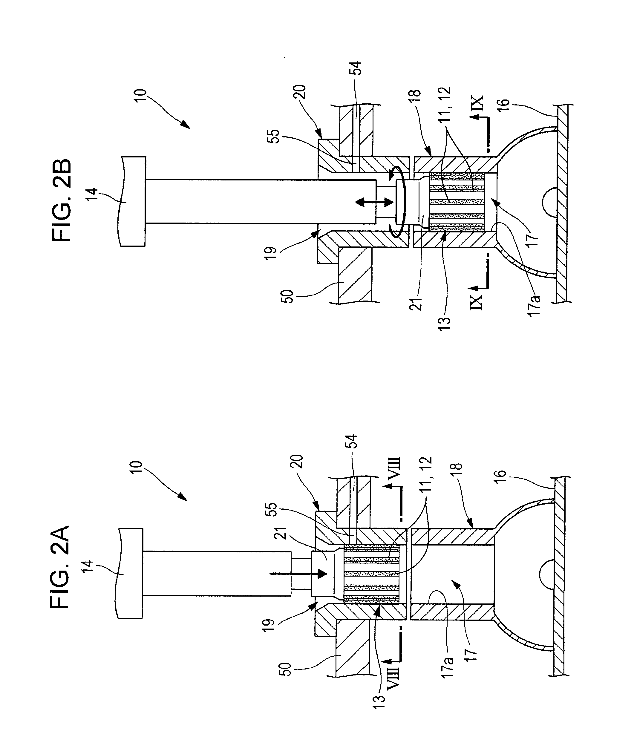
[0025]Embodiments of the present invention will be described below with reference to the drawings. FIG. 1 schematically illustrates a honing apparatus 10 according to an embodiment of the present invention. FIGS. 2A and 2B illustrate an operating process of the honing apparatus 10. As shown in FIG. 1, the honing apparatus 10 includes a rotary tool 13 having honing grindstones 11 and 12 on the outer periphery thereof, a driving unit 14 that drives the rotary tool 13, and a control unit 15 that outputs a control signal to the driving unit 14. The driving unit 14 has a built-in electric motor or actuator (not shown). The driving unit 14 can rotate the rotary tool 13 in the direction indicated by an arrow α, as well as vertically move the rotary tool 13 in the direction indicated by an arrow β. The honing apparatus 10 has a processing table 16 on which a cylinder block (workpiece) 18 having a cylinder bore 17 is mounted. Furthermore, the honing apparatus 10 has a tool guide 20 having a ...


PUM


Abstract

A rotary tool of a honing apparatus is provided with honing grindstones that grind a cylinder bore, and guide members that slide in a guide hole of a tool guide. The guide members are each constituted of a base member fixed to the tool body and a slide member fixed to the base member. The base member is composed of a ceramic material, and the slide member is composed of a cemented carbide material. With the guide members having such a configuration, electrolytic dressing is performed on the honing grindstones.

Description

CROSS REFERENCES TO RELATED APPLICATIONS[0001]The present application claims priority from Japanese Patent Application No. 2011-049016 filed on Mar. 7, 2011, the entire contents of which are hereby incorporated by reference.BACKGROUND OF THE INVENTION[0002]1. Field of the Invention[0003]The present invention relates to a honing apparatus including a rotary tool that grinds an inner cylindrical surface to be formed in a workpiece and a tool guide that guides the rotary tool to the inner cylindrical surface.[0004]2. Description of the Related Art[0005]Cylinder blocks of engines have cylinder bores that accommodate pistons in a slidable manner. The inner surface of a cylinder bore is honed by using a rotary tool equipped with a honing grindstone. If clogging or shedding occurs on the honing grindstone, the cylinder bore cannot be properly ground, resulting in reduced processing accuracy for the cylinder bore. In order to maintain the processing accuracy for the cylinder bore, it is nec...

Claims


Application Information

Patent Timeline
Patent Type & Authority Applications(United States)
IPC IPC(8): B24B33/02
CPCB24B53/001B24B33/02
Inventor YAMAMOTO, YASUTAKA
Owner SUBARU CORP
Learn More