
Systems and methods for powering a charging circuit of a communications interface

a technology of communication interface and charging circuit, which is applied in the direction of electric vehicles, baseband system details, transportation and packaging, etc., can solve the problems of prolonging battery life and consumption, and achieve the effects of minimizing power consumption of electronic circuits, reducing consumption, and reducing consumption

Active Publication Date: 2012-09-13
ANALOGIX SEMICON
View PDF3 Cites 71 Cited by
  • Summary
  • Abstract
  • Description
  • Claims
  • Application Information

AI Technical Summary

Benefits of technology

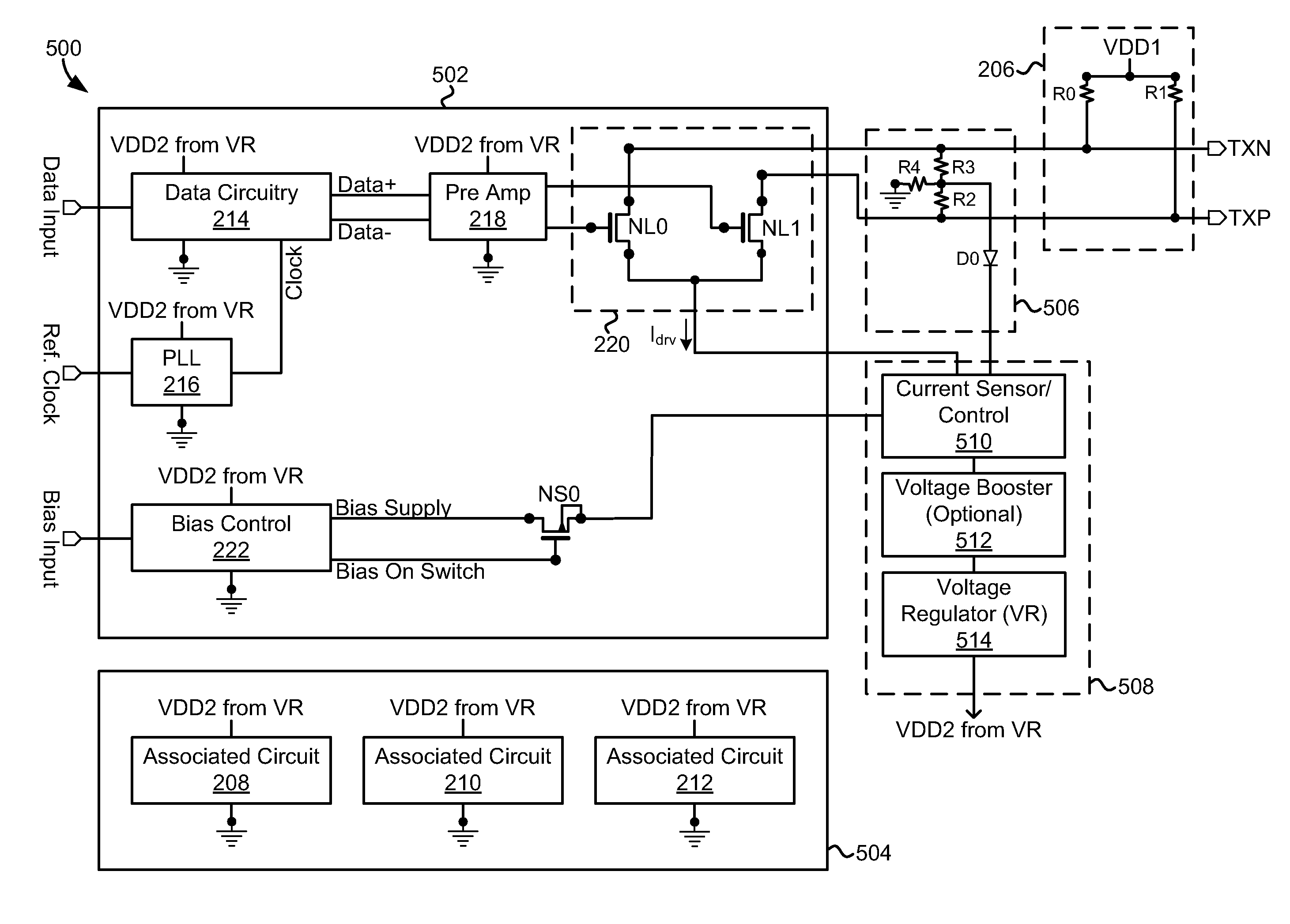
[0006]There is a need to minimize power consumption of electronic circuits such as those used in a data communications system. By minimizing power consumption of electronic circuits, energy can be conserved. In electronic circuits powered by a battery, reducing power consumption lengthens battery life. Reducing power consumption can also reduce energy expenses. Power consumption of electronic circuits such as those used in a data communications system may be minimized by a system including an electronic circuit configured to power another electronic circuit, or using a method of powering an electronic circuit using another electronic circuit.
[0007]Various embodiments of the invention enable power that is first used to establish bias conditions at a transmission line or transmission line driver circuitry to be further used to power additional electronic circuits. By using power first used to establish bias conditions for additional purposes, overall power consumption is reduced compared to the prior art.

Problems solved by technology

In electronic circuits powered by a battery, reducing power consumption lengthens battery life.

Method used


Image

  • Systems and methods for powering a charging circuit of a communications interface
  • Systems and methods for powering a charging circuit of a communications interface
  • Systems and methods for powering a charging circuit of a communications interface

Examples


Embodiment Construction

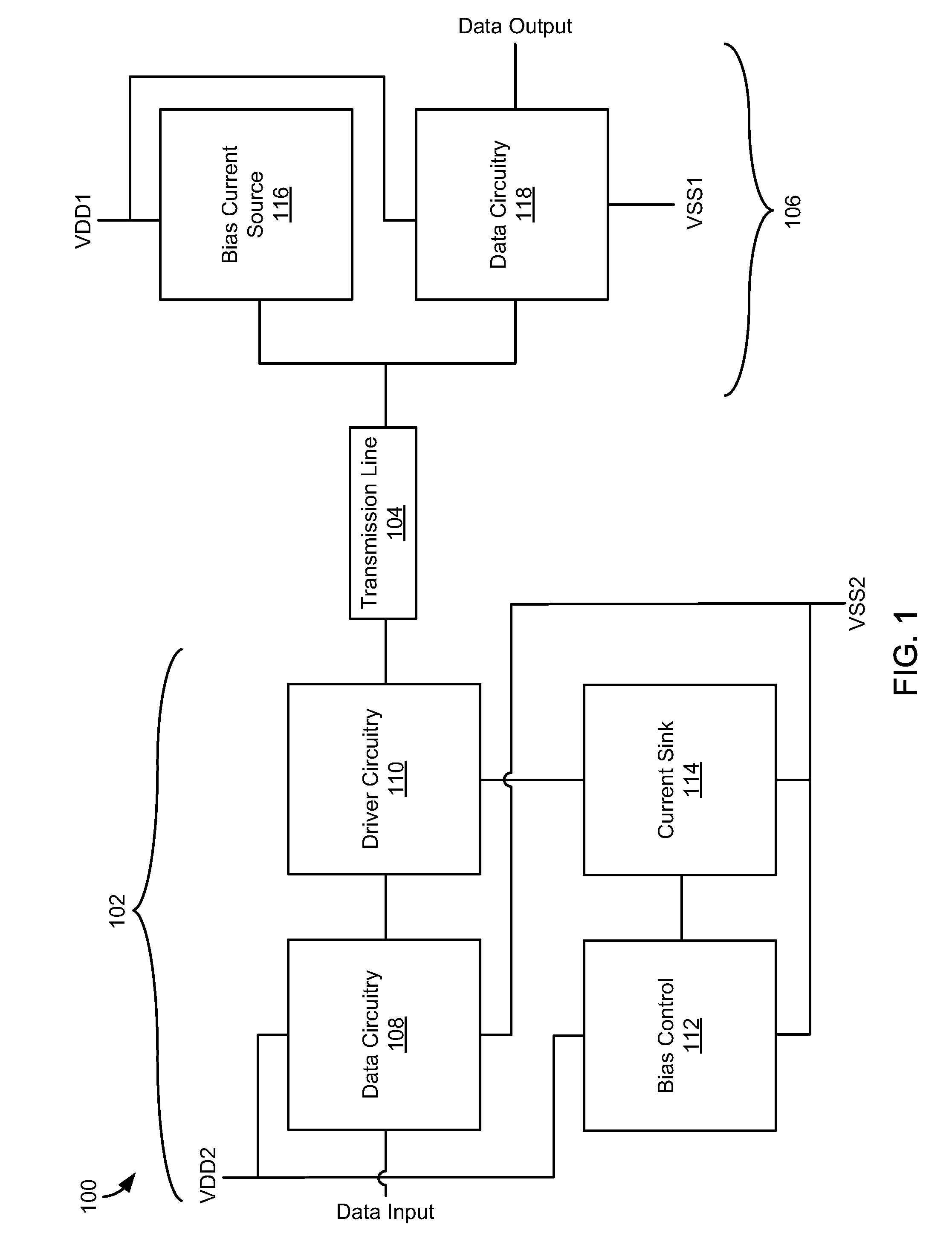
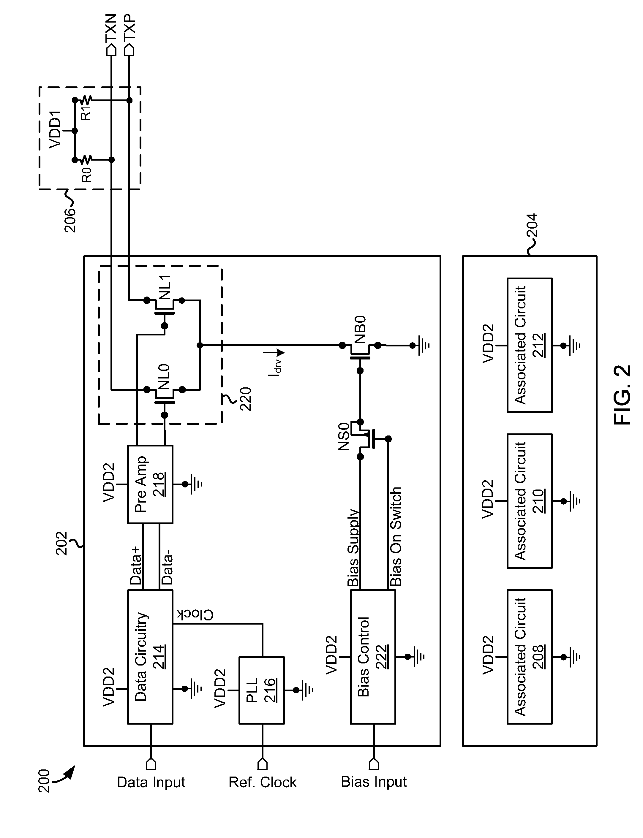
[0025]The present invention includes, in various embodiments, systems and methods of powering a data communications interface. The communications interface may be configured to communicate digital data provided at a transmitter module input port at one end of a transmission line such that the digital data is output at a receiver module output port on an opposite end of the transmission line. The digital data may be transmitted for display on a video display and / or audible reproduction via an audio amplifier. The communications interface may include electronic circuits that consume electrical power by passing electrical current through active and passive electronic devices while communicating the digital data. The communications interface may be representative of a high-definition multimedia interface (HDMI) transmission system, Digital Visual Interface (DVI) transmission system, DisplayPort transmission system, or the like. For example, a transmitter input port may be coupled with e...


PUM


Abstract

Embodiments include systems and methods of powering a mobile device using a sink device. The method may include detecting a coupling of a mobile device to the sink device and transmitting an acknowledgement in response to a query, the acknowledgement confirming that the sink device has charging capability. Power may be selectively provided in response to the power request. According to some embodiments, the method includes transmitting a query by a communications transmitter to determine if a sink device has charging capability, and deactivating a driver for a power line and transmitting a power request using the communications transmitter in response to receiving an acknowledgement signal from the sink device. The method may further include selectively providing power received from the sink device to a charging circuit of the mobile device. The mobile device may include an HDMI transmitter for communicating through a transmission line to an HDMI sink device.

Description

CROSS-REFERENCE TO RELATED APPLICATIONS[0001]This application is a continuation-in-part of U.S. patent application Ser. No. 13 / 278,144, filed on Oct. 20, 2011; which is a divisional of U.S. patent application Ser. No. 12 / 220,411, filed on Jul. 23, 2008, which claims the priority benefit of U.S. Provisional Application No. 60 / 997,853, filed on Oct. 5, 2007, and is a continuation-in-part of U.S. patent application Ser. No. 11 / 820,745, filed on Jun. 19, 2007, which is a continuation-in-part of U.S. patent application Ser. No. 11 / 800,861, filed on May 7, 2007, all of which are incorporated herein by reference.BACKGROUND[0002]1. Field of the Invention[0003]The present invention relates, in general, to the field of powering electronic components. In particular, the present invention relates to powering circuits for a communications interface.[0004]2. Related Art[0005]In a typical data communications system, a transmission line between a transmitter and a receiver is biased at an intended ...

Claims


Application Information

Patent Timeline
IPC IPC(8): H02J7/00
CPCH04L25/02H02J7/00H04L1/16H04L25/028
Inventor ZHU, NINGCHI, HONGWU
Owner ANALOGIX SEMICON
Learn More