
Energy-saving central heating and hot water supply system

a technology of central applied in space heating and ventilation, lighting and heating apparatus, heating types, etc., can solve the problems of increasing the installation area of equipment for heating and hot water supply, reducing the entire capacity of heat source equipment, and reducing efficiency, so as to improve the use efficiency of hot water supplied, minimize heat loss, and save energy

Active Publication Date: 2012-09-13
GU SUNG ENG & CONSTR
View PDF63 Cites 12 Cited by
  • Summary
  • Abstract
  • Description
  • Claims
  • Application Information

AI Technical Summary

Benefits of technology

"The present invention provides an energy-saving central heating and hot water supply system that improves the use efficiency of hot water, reduces heat loss, and saves construction costs. The system includes a main heat exchanger, circulation pump, hot water supply heat exchanger, integrated hot water supply main pipe, hot water collection main pipe, heating water supply heat exchanger, hot water supply heat exchanger for each household or floor, first and second valves, controller, and bypass pipe. The system also allows for the distribution of hot water to each household or floor based on the required temperature, reducing excessive energy consumption. The system also includes a pipeline control unit that distributes heating water to the hot water distributor and the bypass pipe at a predetermined ratio. The technical effects of the invention include improved energy efficiency, reduced heat loss, and reduced operating costs."

Problems solved by technology

Thus, the central heating and hot water supply system can actively prevent the decrease of efficiency, caused by the long continuous use of the heat source equipment, and reduce the entire capacity of the heat source equipment, as compared with the individual heating and hot water supply system.
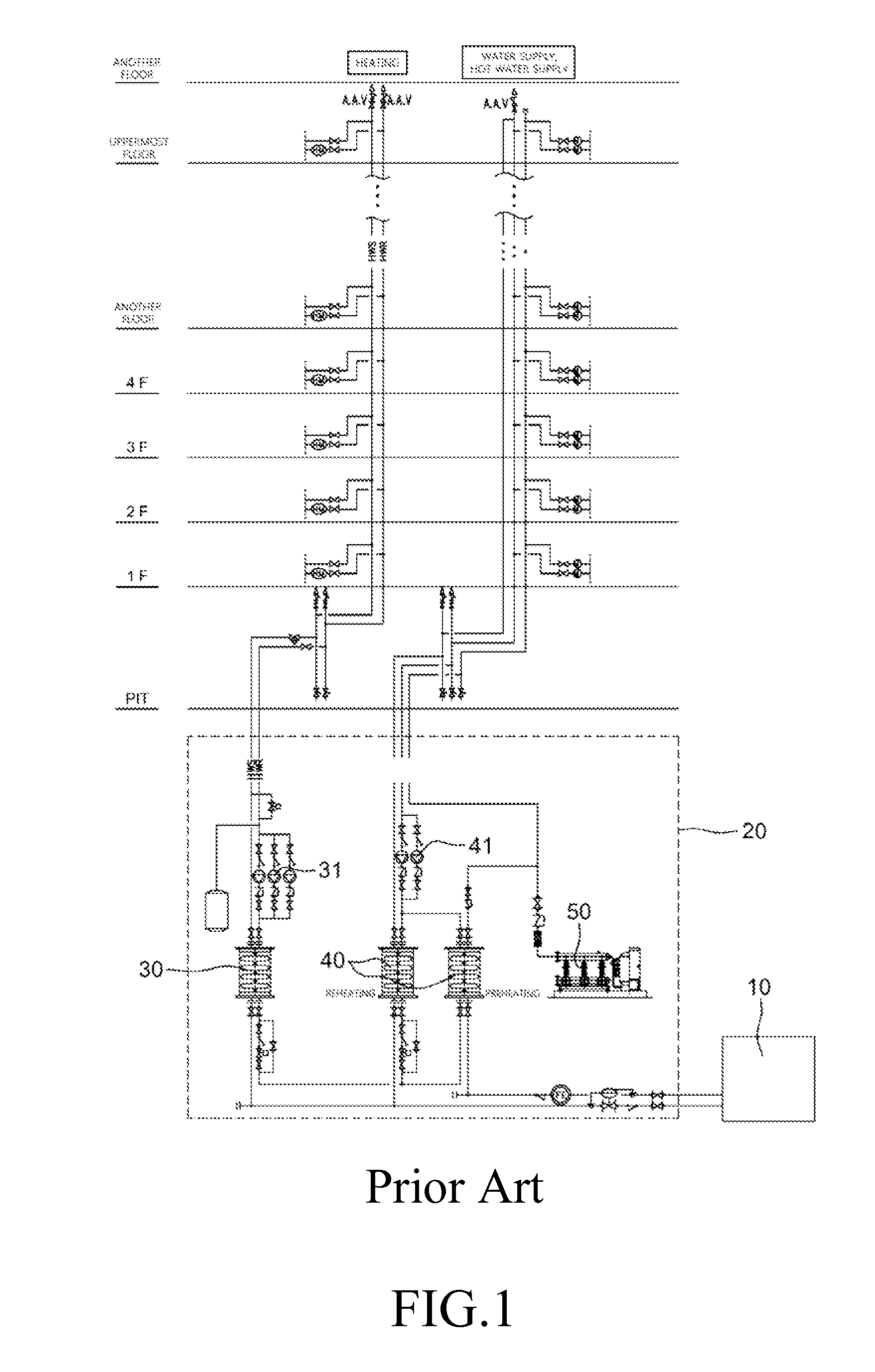
However, in the central heating and hot water supply system, the installation area of equipment for heating and hot water supply increases, and the cost of equipment increases more than that in the individual heating and hot water supply system.
Further, civil complaints may occur due to an increase in cost of piping equipment and occurrence of maintenance and operating expenses.
Therefore, heat loss through the pipes is large (it is typically identified that up to 10 to 30% of the heat of the entire hot water supply energy is lost), and power consumption for fluid transfer is large.
Since more pipe installation cost is required to connect between the machine room and each household, the cost of construction work increases.
For this reason, if the thermal capacity of the heated water is not efficiently radiated, the effect of improvement may be insignificant.
Furthermore, unreasonable energy loss may be caused due to excessive equipment capacity, or the like.
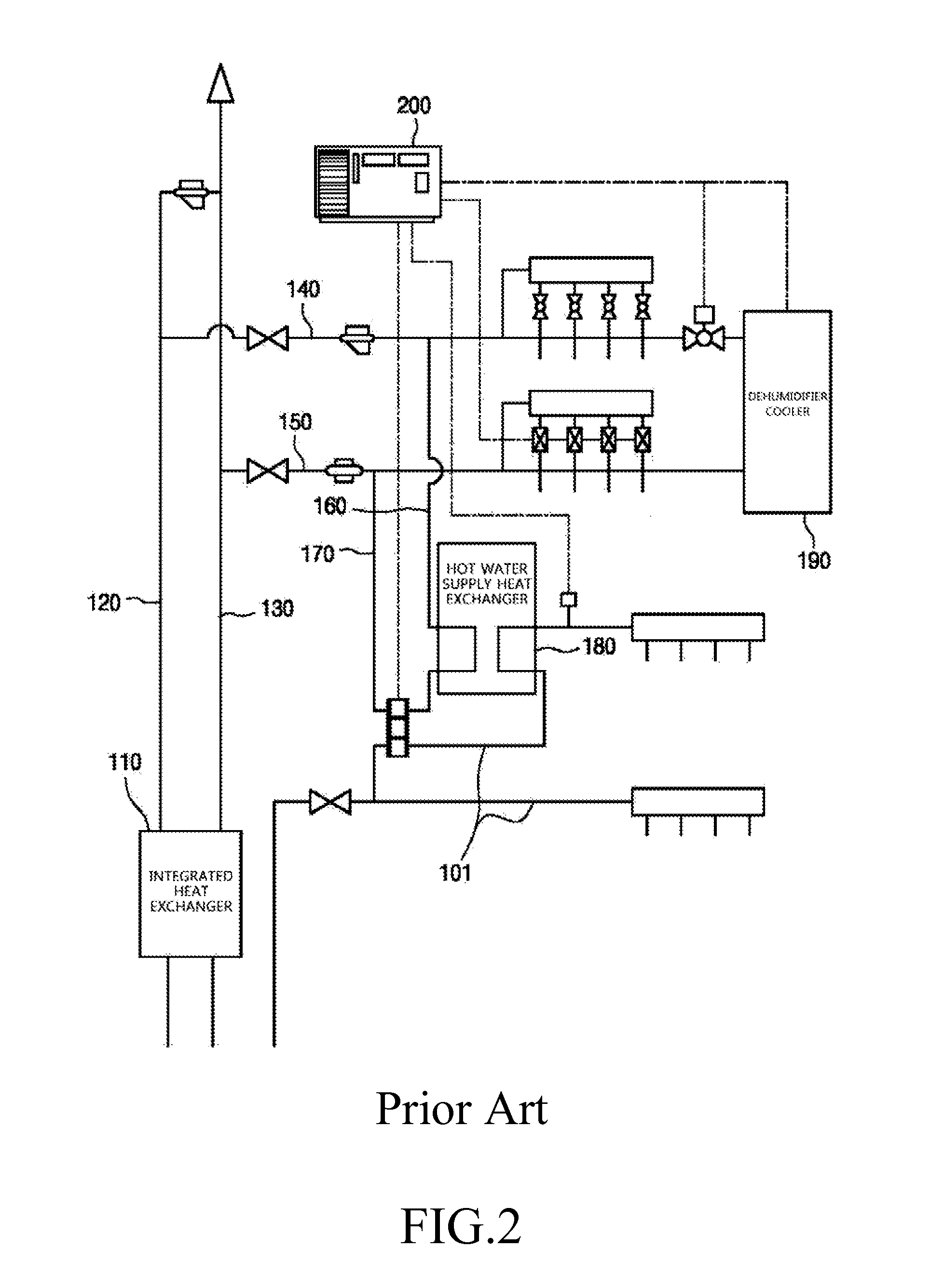
That is, since heated water is collected at a relatively high temperature in the process of collecting the heated water to the integrated heat exchanger after heating or producing hot water through the heat exchanger, the integrated pipe system in the apartment house and building has a problem of limited energy savings, such as a large amount of heat loss due to a great difference in temperature between the inside and outside of the pipe.
Therefore, various problems may occur due to surplus heat capacity or flow rate supplied when the hot water supply and heater are not simultaneously used to the maximum load, particularly when demand on hot water supply is decreased or does not occur.
As a result, floor noise may occur due to an increase of flow velocity in a heating pipe installed in the floor, caused by an excess amount of circulation water, and the total heat effectiveness of radiant heating in the floor may be decreased.

Method used


Image

  • Energy-saving central heating and hot water supply system
  • Energy-saving central heating and hot water supply system
  • Energy-saving central heating and hot water supply system

Examples


Embodiment Construction

[0045]The present invention is described more fully hereinafter with reference to the accompanying drawings, in which embodiments of the present invention are shown. This present invention may, however, be embodied in many different forms and should not be construed as limited to the embodiments set forth herein. Rather, these embodiments are provided so that this disclosure is thorough, and will fully convey the scope of the present invention to those skilled in the art.

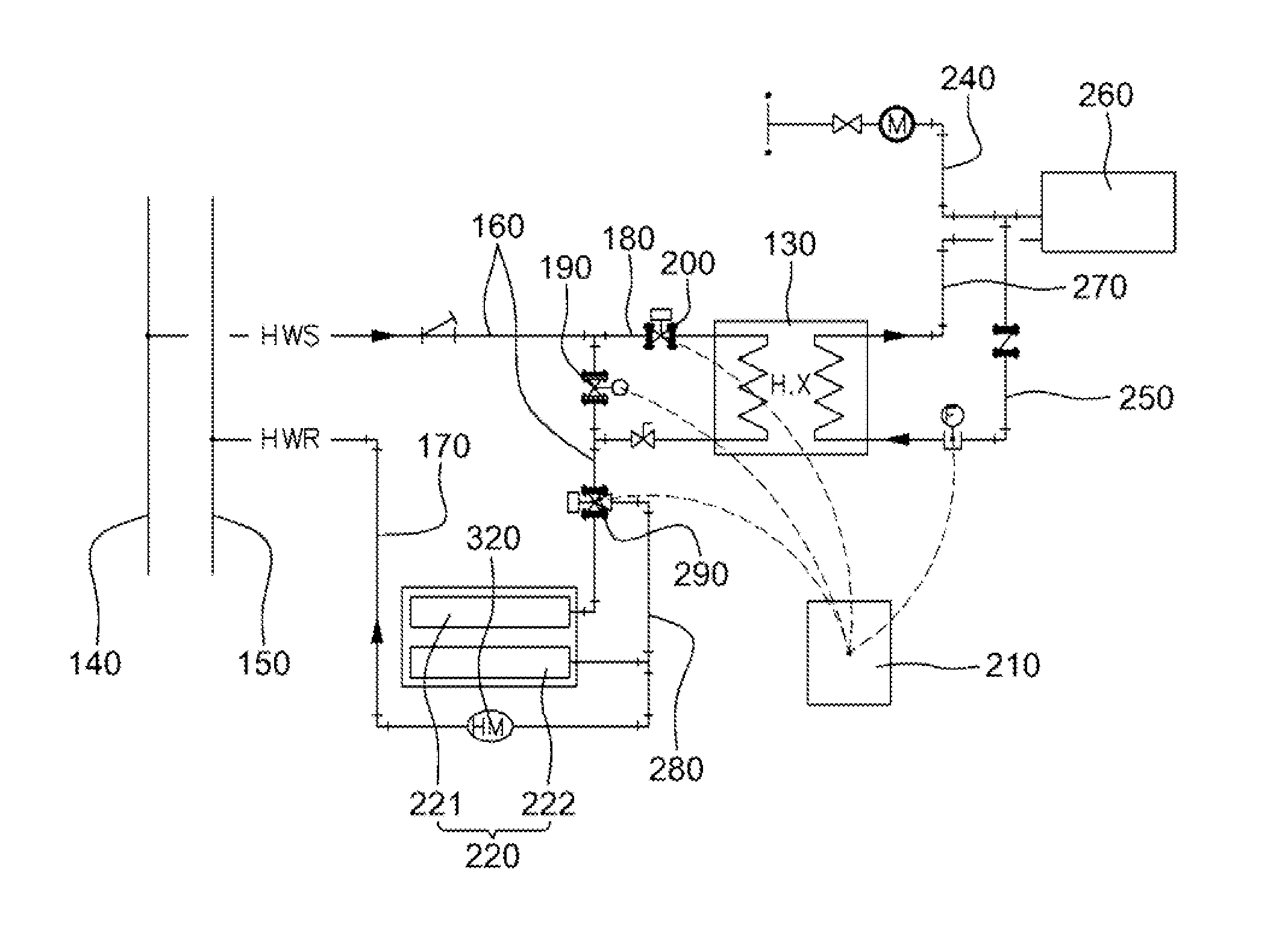
[0046]FIG. 3 is a structural view of a central heating and hot water supply system according to an embodiment of the present invention. FIG. 4 is a structural view specifically showing a main part of the central heating and hot water supply system according to the embodiment of the present invention.

[0047]In the central heating and hot water supply system according to this embodiment, when hot water is produced for each household or floor using heating water supplied for the purposed of heating of each household or ...


PUM


Abstract

An energy-saving heating and hot water supply system includes a main heat exchanger, a circulation pump, a hot water supply heat exchanger and a hot water distributor. The main heat exchanger produces heating water through a heat exchange. The circulation pump circulates the heating water produced in the main heat exchanger so that the heating water is supplied to and collected from each household or floor. The hot water supply heat exchanger produces hot water through a heat exchange between water for hot water supply and the heating water supplied from the main heat exchanger and circulates the produced hot water in a floor coil through the hot water distributor or directly circulates the produced hot water in the floor coil. The hot water distributor receives the heating water and circulates the received heating water in the floor coil provided for each household or floor.

Description

CROSS-REFERENCE TO RELATED APPLICATION[0001]This application claims the benefit of Korean Patent Application No. 10-2010-0021330, filed Mar. 10, 2011, the disclosure of which is hereby incorporated herein by reference in its entirety.BACKGROUND OF THE INVENTION[0002]1. Field of the Invention[0003]An aspect of the present invention relates to a central heating and hot water supply system for receiving a heat source such as steam or high-temperature water obtained from a medium- or large-sized boiler, a heat source obtained from nature such as sunlight, or a heat source obtained from waste heat of an electric generator or boiler, producing hot water through a heat exchange, and supplying the hot water from small- and medium-scale buildings to large-scale buildings using a central supply method. More particularly, an aspect of the present invention relates to an energy-saving central heating and hot water supply system which can simplify pipeline equipment for supplying hot water to ea...

Claims


Application Information

Patent Timeline
Patent Type & Authority Applications(United States)
IPC IPC(8): F28F27/00F28F27/02
CPCF24D3/02F24D19/1069F24D19/1066F24D3/087Y02P80/10F24D3/00F24D3/10F24D19/10F24D19/08
Inventor YUN, SOK KU
Owner GU SUNG ENG & CONSTR
Learn More