
Method and system for recycling and treating dyeing wastewater

a technology for applied in water/sewage multi-stage treatment, filtration separation, separation process, etc., can solve the problems of high cost, large amount of sludge, and inability to dehydrate sludge by distillation, etc., and achieve the effect of efficient recycling and treating dyeing wastewater and low cos

Inactive Publication Date: 2012-09-06
IANG JR JUNG
View PDF13 Cites 14 Cited by
  • Summary
  • Abstract
  • Description
  • Claims
  • Application Information

AI Technical Summary

Benefits of technology

[0008]It is an objective of the present invention to provide a method and system for recycling and treating dyeing wastewater efficiently and at low costs, wherein the method and system not only solve problems with effluent chromaticity effectively but also provide secondary treatment to concentrated wastewater.
[0012]Step (C): The wastewater having undergone the assisted decolorization is passed through the first filtration device for filtration treatment, with a view to reducing the chromaticity and suspended solid content of the wastewater.
[0018]In order to minimize clogging and fouling of the RO membranes, the present invention entails using an adsorbent to assist in dehydration and filtration of dyeing wastewater and performing a hydrophilic membrane-based pre-treatment filtration process on the dyeing wastewater before the RO membrane-based filtration process is conducted. Moreover, a micro-bubbling process is performed on the concentrated wastewater discharged during the RO membrane-based filtration process, and a solid-liquid separation process is subsequently performed by means of hydrophobic membranes so as for the chromaticity, BOD, and COD of the resultant effluent to meet existing effluent standards. The use of hydrophobic membranes and the revolution thereof not only extend membrane operation lifecycle effectively, but also enable quick and efficient operation, reduce the required amount of additives, and lower operation costs.

Problems solved by technology

These two treatment processes, however, end up with a large amount of sludge whose water content is so high that the sludge can only be dehydrated by distillation.
As a result, the conventional method for treating dyeing wastewater is energy-intensive and cost-incurring.
Besides, the chromaticity of the processed effluent is too high to meet the existing effluent chromaticity standard recommended by the American Dye Manufacturers Institute (ADMI).
Therefore, dyeing wastewater decolorization technology has become an environmental protection issue that draws attention from the dyeing industry.
However, as dyeing wastewater contains a large amount of suspended substances, if the dyeing wastewater does not undergo a proper pre-treatment process, the RO membranes are subject to concentration polarization and may produce oxidized crystals.
Even worse, the efficiency of filtration may dwindle to an incapacitated level because of a cake layer formed on the membrane surface or because of plugged membrane pores.
Hence, RO requires expensive apparatuses and incurs high operation costs.
More importantly, the concentrated wastewater resulting from RO cannot be treated again by RO membranes for solid-liquid separation; the dyeing industry can only perform multi-stage distillation dehydration on the concentrated wastewater so as for the ions therein to crystallize.
The latter process, however, is energy-intensive and time-consuming and thus poses a thorny problem.
Nonetheless, the aforesaid processes are focused on the removal of dyeing chromaticity from wastewater but do not offer an efficient and cost-saving solution to treating the resultant concentrated wastewater (or sludge).
In consequence, the dyeing industry is confronted with increasingly high costs for environmental protection and improvement.

Method used


Image

  • Method and system for recycling and treating dyeing wastewater
  • Method and system for recycling and treating dyeing wastewater
  • Method and system for recycling and treating dyeing wastewater

Examples


Embodiment Construction

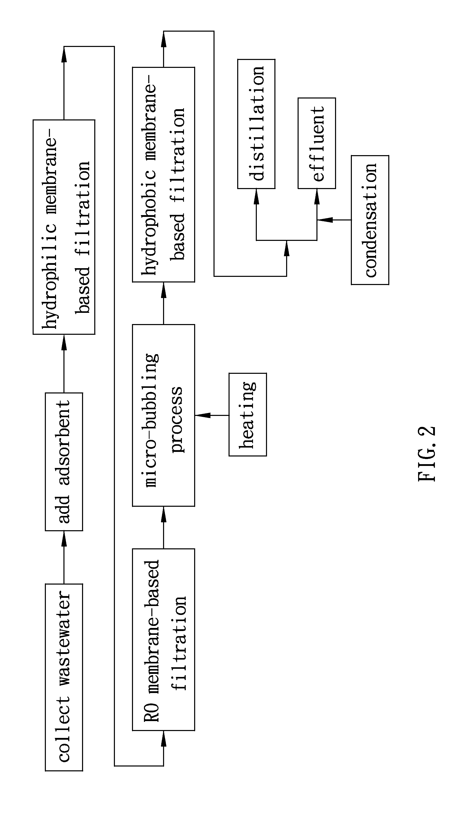
[0025]Please refer to FIG. 2 and FIG. 3 for a method and system for recycling and treating dyeing wastewater according to a first embodiment of the present invention. As shown in FIG. 2, the method comprises the following steps:

[0026]Step (A): Dyeing wastewater is collected and guided into a pre-treatment tank 10 for subsequent treatment.

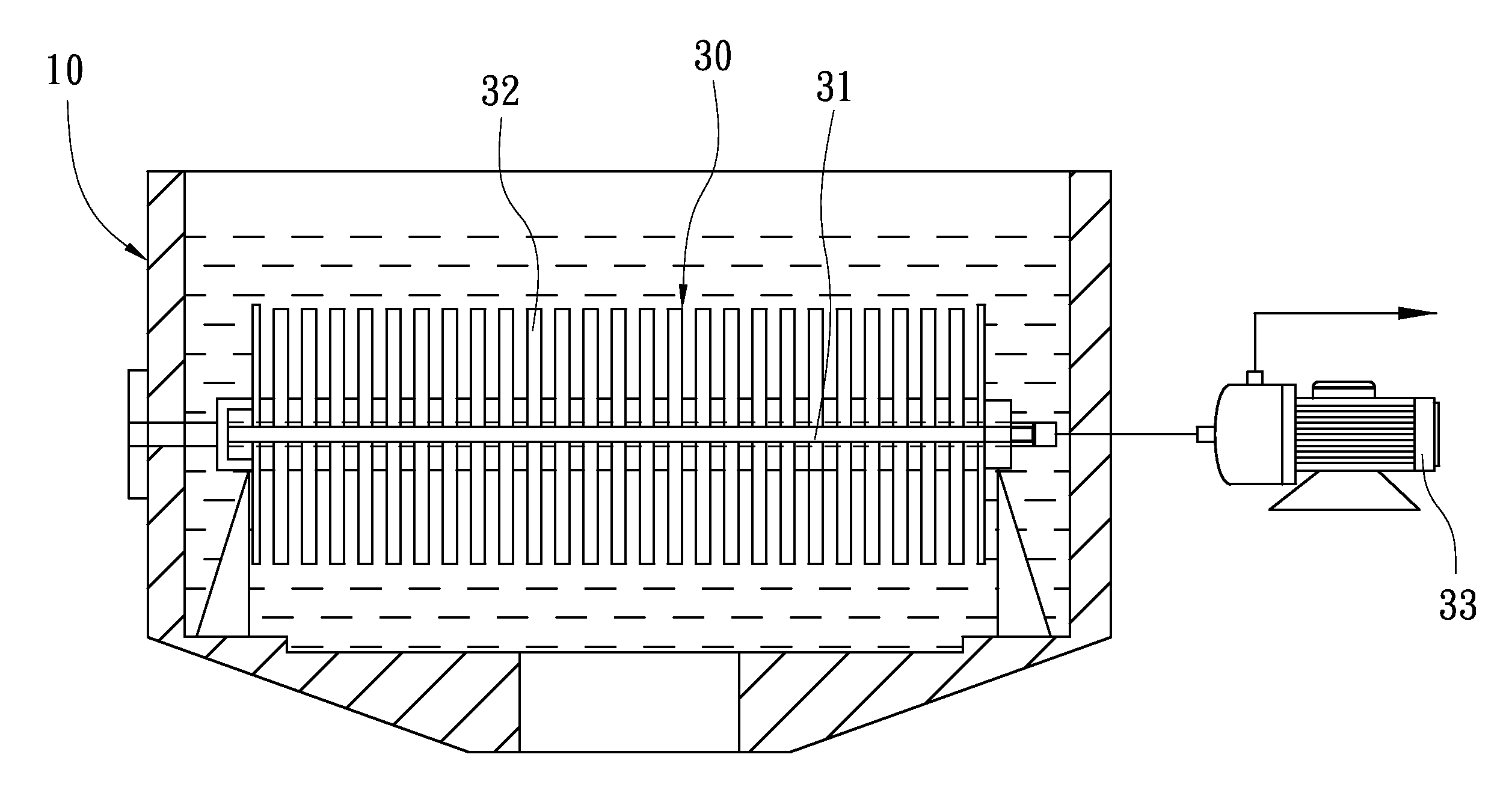
[0027]Step (B): An appropriate amount of adsorbent 20 is added into the pre-treatment tank 10, wherein the adsorbent 20 is one of diatomite, activated carbon, and zeolite powder. The adsorbent 20 is quickly mixed with the dyeing wastewater so as for the adsorbent 20 to adsorb the dyes and suspended particles in the dyeing wastewater and thereby assist in decolorization and filtration of the dyeing wastewater. The pre-treatment tank 10 is provided therein with a first filtration device 30. Referring to FIG. 4, the first filtration device 30 is transversely disposed and submerged in the pre-treatment tank 10. The first filtration device 30 comprises a...


PUM

PropertyMeasurementUnit
Temperatureaaaaaaaaaa

Abstract

A method and system for recycling and treating dyeing wastewater are provided. To begin with, the dyeing wastewater is added with an adsorbent for assisted decolorization and filtration. Then, the wastewater is filtered with a first filtration device having hydrophilic membranes. The liquid having passed through the hydrophilic membranes undergoes an RO membrane-base filtration process to produce recycled water and concentrated wastewater. The concentrated wastewater is delivered into a second filtration device having hydrophobic membranes, before a micro-bubbling process is performed on the concentrated wastewater in the second filtration device to turn the concentrated wastewater into a creamy-white nebulized working liquid of high gas content. The steam in the working liquid can readily pass through the hydrophobic membranes to produce an effluent that meets effluent standards.

Description

BACKGROUND OF THE INVENTION[0001]1. Field of the Invention[0002]The present invention relates to wastewater treatment methods and systems, and more particularly, to a method and system for recycling and treating dyeing wastewater efficiently and at low costs, wherein the method and system are effective in solving problems found with effluent chromaticity.[0003]2. Description of the Related Art[0004]As the dyeing industry requires the use of various dyes, surfactants, and chemical agents, dyeing wastewater is characterized by high chromaticity, marked variation in water quality, and low biodegradability. Therefore, dyeing wastewater has to be treated by both biological and chemical processes in order to reduce biochemical oxygen demand (BOD), chemical oxygen demand (COD), suspended solids (SS), and chromaticity of the dyeing wastewater.[0005]A conventional method employed by most dyeing factories in Taiwan to treat dyeing wastewater essentially comprises, as shown in FIG. 1, the step...

Claims


Application Information

Patent Timeline
IPC IPC(8): C02F1/44C02F11/12C02F11/13
CPCC02F1/04C02F1/281C02F1/283C02F1/441C02F1/444C02F2303/26C02F1/76C02F9/00C02F11/12C02F2103/30C02F1/74C02F11/13
Inventor IANG, JR-JUNG
Owner IANG JR JUNG
Learn More