
Display casing and cover structure thereof

Active Publication Date: 2012-08-30
AMTRAN TECH
View PDF10 Cites 10 Cited by
  • Summary
  • Abstract
  • Description
  • Claims
  • Application Information

AI Technical Summary

Benefits of technology

[0008]In view of the above-mentioned problems, the present invention is a display casing and a cover structure thereof, thereby solving the problem existing in the display casing in the prior art that hooks of a plastic outer cover are easily fractured from the plastic outer cover or damaged in the course of being buckled on buckling pieces of a metal back cover during the assembly of the plastic outer cover and the metal back cover.
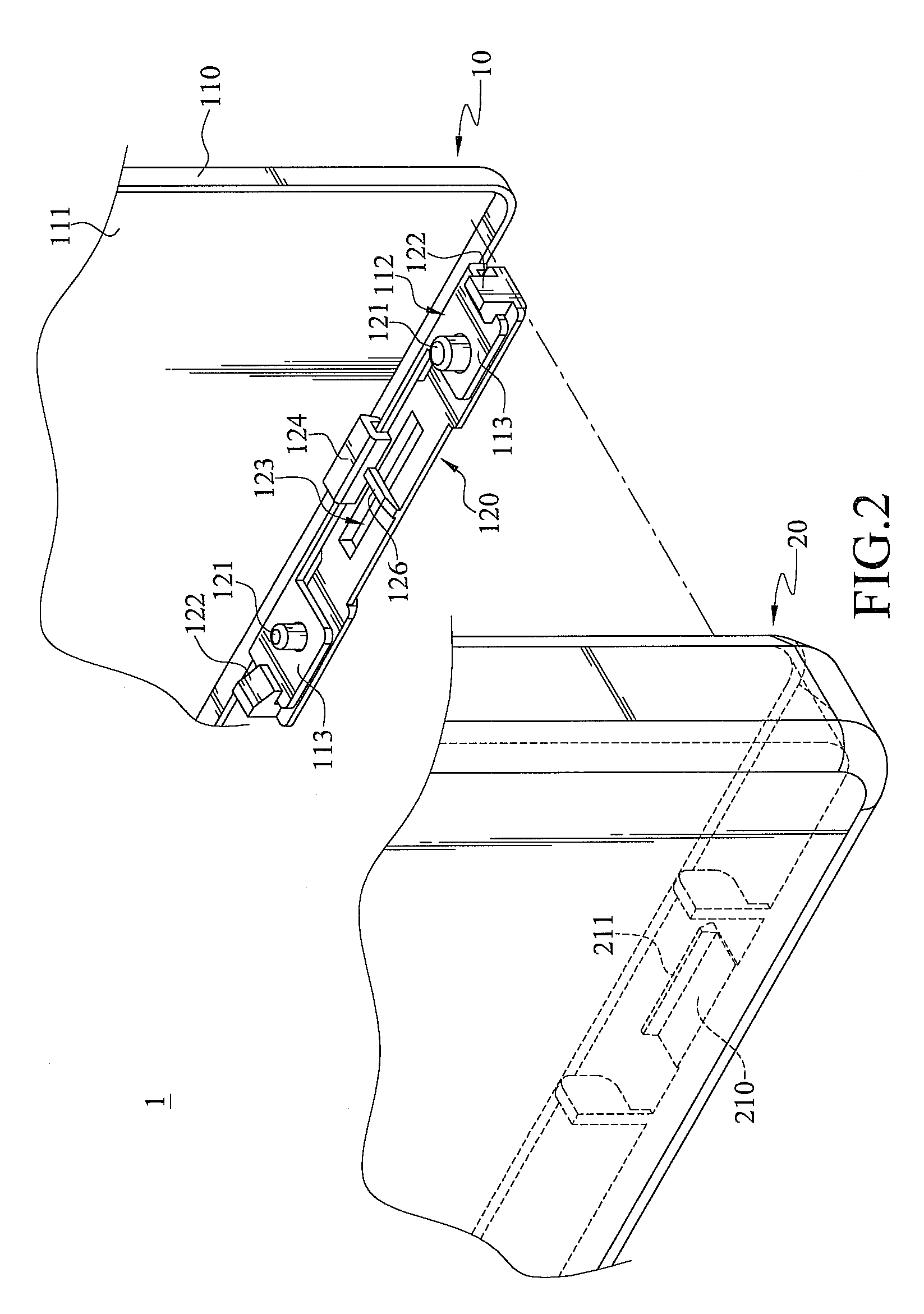
[0012]The present invention has at least one of the following effects. The material of the fixing members is similar to or the same as that of the second cover, and the fixing members are disposed on the first cover. Therefore, when the second cover is combined with the first cover, bending deformation may be generated by the resilience of the materials of the second cover and the fixing members, thereby avoiding the fixing members fractured from the first cover due to the pushing force applied by the second cover. Moreover, the fixing members have positioning pins and / or restraining portions respectively, and the cover body of the first cover has the budding pieces and the connecting holes correspondingly, so that the fixing members can be quickly assembled on the first cover, thereby the assembly time of the first cover is reduced and the assembly efficiency of the display casing is improved.

Problems solved by technology

However, the material of the hooks is different from the buckling pieces.
The hooks must bear both the downward force and the reaction force, and such interaction of the downward force and reaction force may cause the fracture of the hooks due to over stress.
Accordingly, such fractures of the hooks may further cause that a loose combination exists between the plastic outer cover and the metal back cover, or that the plastic outer cover cannot be engaged to the metal back cover.

Method used


Image

  • Display casing and cover structure thereof
  • Display casing and cover structure thereof
  • Display casing and cover structure thereof

Examples


Embodiment Construction

[0021]The present invention will now be described more fully hereinafter with reference to the accompanying drawings, in which exemplary embodiments of the invention are shown. This invention may, however, be embodied in many different forms and should not be construed as limited to the embodiments set forth herein. Rather, these embodiments are provided so that this disclosure will be thorough and complete, and will fully convey the scope of the invention to those skilled in the art. Like reference numerals refer to like elements throughout.

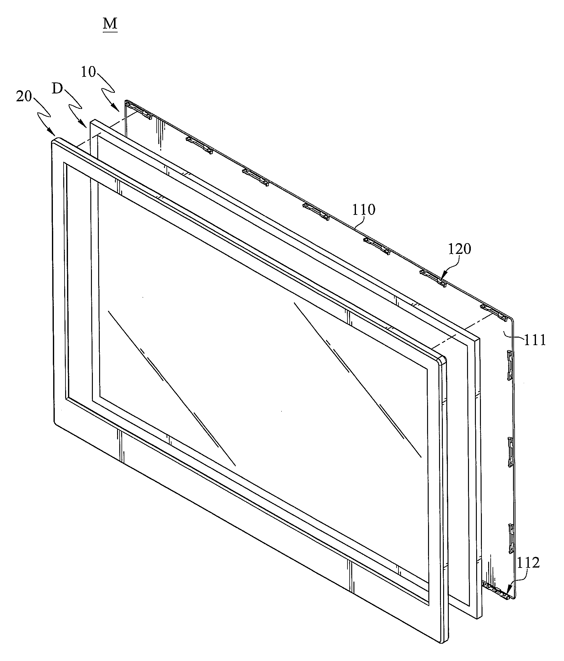
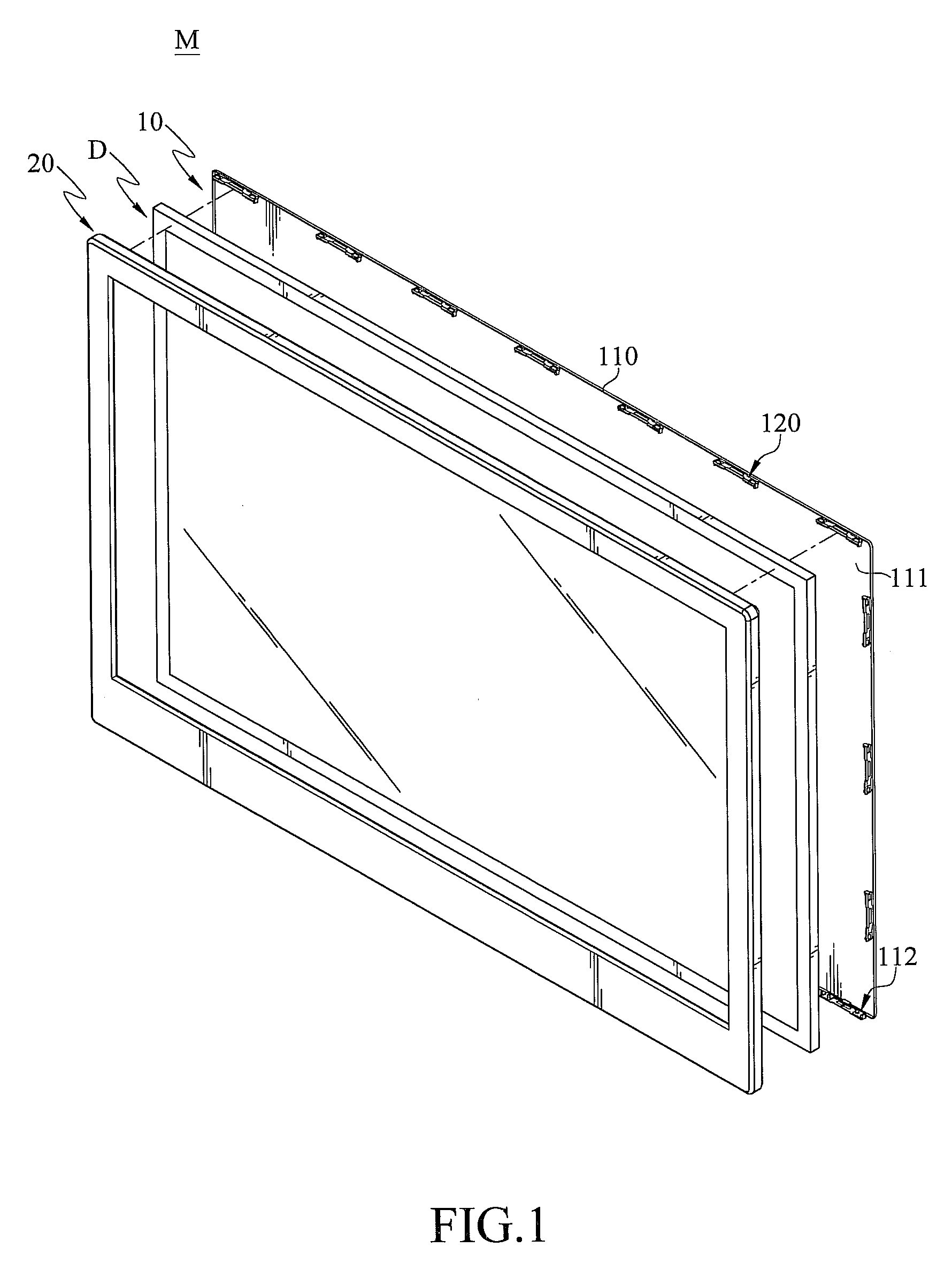
[0022]As shown in FIG. 1 to FIG. 3, a casing 1 of a display device according to an embodiment of the present invention is disclosed. The casing 1 can accommodate a display module D and constitute a display device M. The display device M can be any electronic product having a display, such as a TV set, a computer, a cell phone, a PDA, a GPS and point-of-sale terminals, where the display serves as a viewing interface or operation interface for use...


PUM


Abstract

A display casing has a first cover, a second cover, and a fixing member between the first cover and the second cover to serve as a combination medium therebetween. The fixing member is engaged with two buckling pieces of the first cover by a positioning pin and a restraining portion, and the second cover is then buckled on the fixing member by a buckling member to be combined with the first cover. The material of the fixing member is the same as that of the second cover but is different from, the material of the first cover. Therefore, when the buckling member of the second cover is buckled on the fixing member, the risk of the fracture of the fixing member under the stress of the buckling member can be avoided.

Description

CROSS-REFERENCE TO RELATED APPLICATIONS[0001]This non-provisional application claims priority under 35 U.S.C. §119(a) on Patent Application No(s). 100106516 filed in Taiwan, R.O.C. on Feb. 25, 2011, the entire contents of which are hereby incorporated by reference.BACKGROUND OF THE DISCLOSURE[0002]1. Technical Field[0003]The present invention relates to a casing and a cover structure thereof, and more particularly to a casing of a display device and a cover structure thereof.[0004]2. Related Art[0005]Consumer electronic products, such as TV sets, computers, cell phones, personal digital assistants (PDA), global positioning systems (GPS) and point-of-sale terminals, always have displays which normally serve as viewing interfaces or operation interfaces for users. Generally speaking, a flat panel display device, such as an LCD display or a plasma display, is mainly composed of a casing and a display module. The casing comprises a plastic outer cover and a metal back cover. The plastic...

Claims


Application Information

Patent Timeline
IPC IPC(8): A47B96/00A47B97/00
CPCG06F1/1601G06F1/1637H04M1/0252H05K5/02G06F2200/1612
Inventor WU, CHUANG-MINGLI, TA-WEI
Owner AMTRAN TECH
Learn More