
Vent Assembly For A Grain Bin

a technology for venting and grain bins, which is applied in ventilation systems, lighting and heating apparatus, heating types, etc. it can solve the problems of affecting affecting the ventilation performance of the grain bin, and the proportion of the grain bin roof to deteriorate, so as to prevent the build-up of moisture and debris, and prolong the life of the grain bin roo

Inactive Publication Date: 2012-08-23
SUKUP MFG
View PDF41 Cites 4 Cited by
  • Summary
  • Abstract
  • Description
  • Claims
  • Application Information

AI Technical Summary

Benefits of technology

[0008]A grain bin assembly wherein the grain bin has a corrugated cylindrical wall and a roof structure having a plurality of triangular roof panels. A vent assembly is connected to the roof and has a base. The base has a back wall, two side walls, a front wall and a flange that extends outwardly therefrom. The back wall and sidewalls are generally straight whereas the front wall extends outwardly and is tapered to a point or peak. When connected to the grain bin roof, the peak of the vent assembly is positioned to point upwardly. This peak prevents the build up of moisture and debris thereby extending the life of the grain bin roof.

Problems solved by technology

While roof vent assemblies of this nature facilitate airflow through the roof, they have their drawbacks.
This collection of debris and moisture tend to cause this portion of the grain bin roof to deteriorate, leak or rust-out prematurely.
In addition, the build-up of large amounts of ice during the winter time can cause damage to, or mechanical failure of, the grain bin assembly or the roof itself.
The configuration of these conventional grain bin roof vent assemblies are large, voluminous and cumbersome and take up an undesirable amount of space when shipping.

Method used


Image

  • Vent Assembly For A Grain Bin
  • Vent Assembly For A Grain Bin
  • Vent Assembly For A Grain Bin

Examples


Embodiment Construction

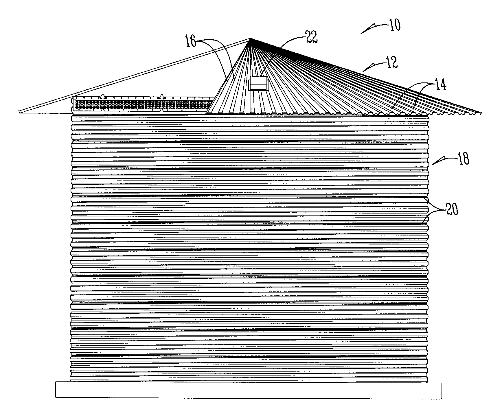
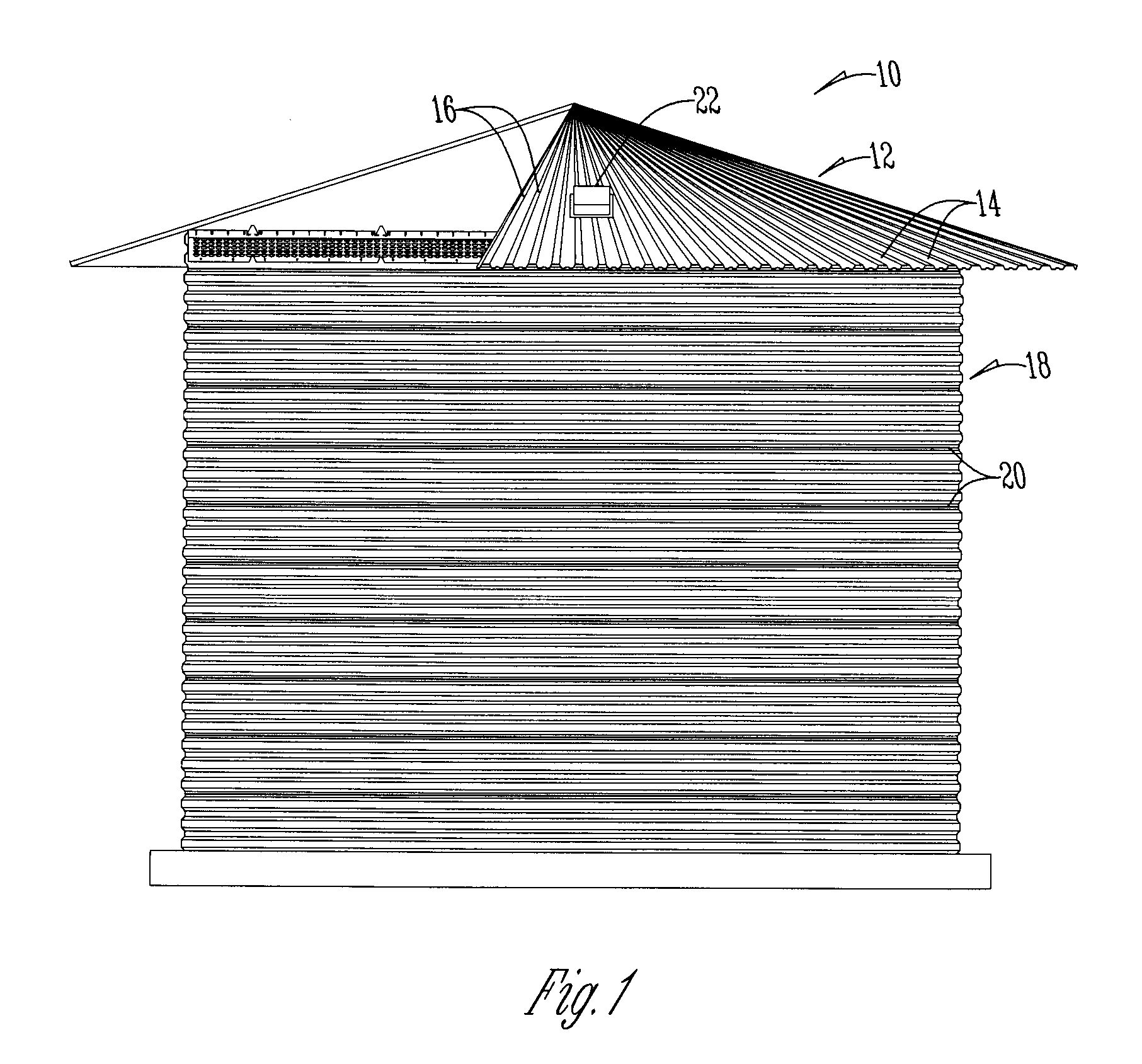
[0018]A grain drying bin 10 has a roof structure 12 having triangular roof panels 14 joined together at rib junctions 16. The bin 10 also has a cylindrical sidewall wall 18 generally formed from corrugated metal panels 20. Connected to the roof 12 is a plurality of roof vent assemblies 22.

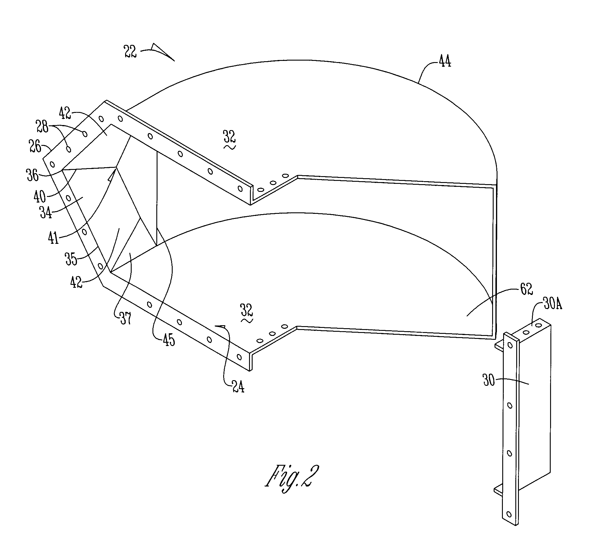
[0019]The vent assembly 22 has a base 24 with an outwardly extending flange 26. The flange 26 has a plurality of apertures 28 used for connection to the roof 12. The base 24 has a back or lower wall 30, sidewalls 32, and a front or top wall 34 that form an enclosure that fits over and is in communication with an opening in the roof assembly. Preferably, back wall 30 is removably attached to the sidewalls 32 by flanges 30A that extend from the back wall toward the front wall 34.

[0020]The front wall 34 has a lower edge 35 that extends from the sidewalls 32 to a point, peak or rounded crest 36. The front wall also has an elongated portion 37 that extends between the sidewalls 32. From point 36, the fr...


PUM


Abstract

A roof vent assembly wherein the grain bin has a corrugated cylindrical wall and a roof structure having a plurality of triangular roof panels. A vent assembly is connected to the roof. The vent assembly has a base. The base has a back wall, two side walls and a front wall which extend upwardly from the flange. The back wall and sidewalls are generally straight whereas the front wall extends outwardly to a point, peak or crest. When connected to the grain bin roof, the peak of the vent assembly is positioned to point upwardly. This peak prevents the build up of moisture and debris thereby extending the life of the grain bin roof assembly.

Description

BACKGROUND OF THE INVENTION[0001]This invention is directed toward a vent for use with a grain bin such as a bin for drying grain or grain storage.[0002]Typically, after a grain bin is filled, air is blown through the bin for grain conditioning purposes. To facilitate this air movement conventional grain bins are equipped with raised and vented floors and roof vents. Air is blown under the raised floor which passes through the grain and out the roof vents. These vents provide a dual purpose as they allow air, dust and moisture to flow out of the grain bin while preventing birds and precipitation from entering the grain bin. In this way, these vents allow a user to condition the grain to an appropriate moisture level and store the grain for long periods of time without spoilage.[0003]Conventional grain bin roofs angle or slope downwardly to protect the grain within. Generally, a grain bin roof has several apertures cut therein to allow air to flow out of the grain bin. These aperture...

Claims


Application Information

Patent Timeline
Patent Type & Authority Applications(United States)
IPC IPC(8): F24F7/02
CPCB65D88/741F24F7/02F24F2221/52A23B9/08A01F25/12A01F25/14A01F25/08
Inventor HANIG, JOHN A.SUKUP, STEVEN E.SUKUP, EUGENE G.SUKUP, CHARLES E.POPPEN, BRADLEY A.
Owner SUKUP MFG
Learn More