
Fuel cell system

Active Publication Date: 2012-08-23
TOYOTA JIDOSHA KK
View PDF0 Cites 3 Cited by
  • Summary
  • Abstract
  • Description
  • Claims
  • Application Information

AI Technical Summary

Benefits of technology

[0015]According to the present invention, a fuel cell system that is capable of suppressing the backflow of the water from the exhaust pipe outlet that discharges the reactant-off gas, without decreasing the performance and fuel consumption of the fuel cell, is provided.

Problems solved by technology

However, when the outside-air temperature is low, the moisture inside the exhaust system freezes, and it may not be possible to continue the operation or restart the operation once it has been stopped.
However, since the gas is always exhausted from two systems, there is a problem in that the amount of electric power generation requested to the fuel cell cannot be ensured depending on the state of the fuel cell system.

Method used


Image

  • Fuel cell system
  • Fuel cell system
  • Fuel cell system

Examples


Embodiment Construction

[0021]An embodiment of the present invention will be described below with reference to the attached drawings. In order to easily understand the descriptions, corresponding reference numerals are assigned to corresponding components wherever possible in each drawing and any redundant descriptions will be omitted.

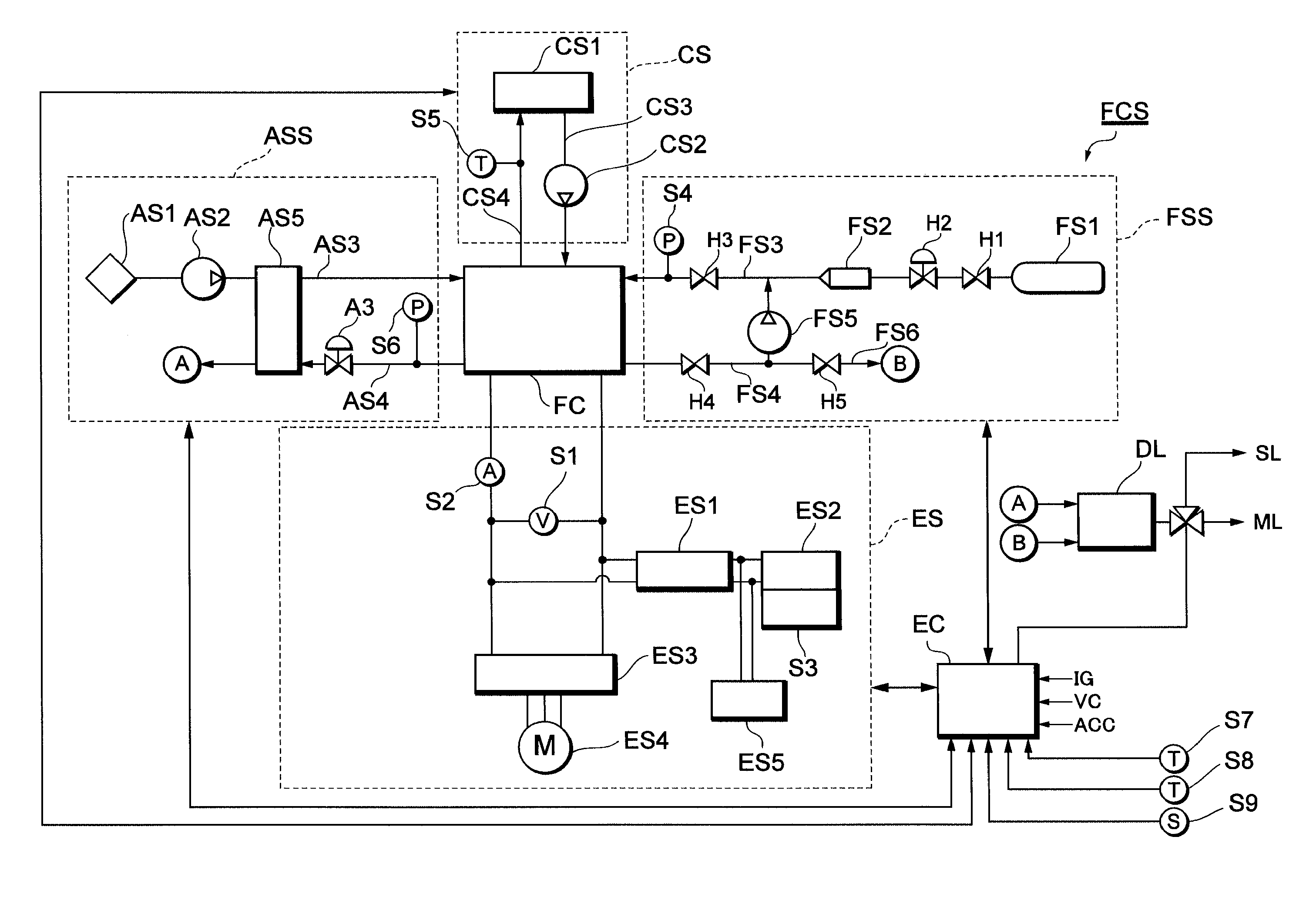
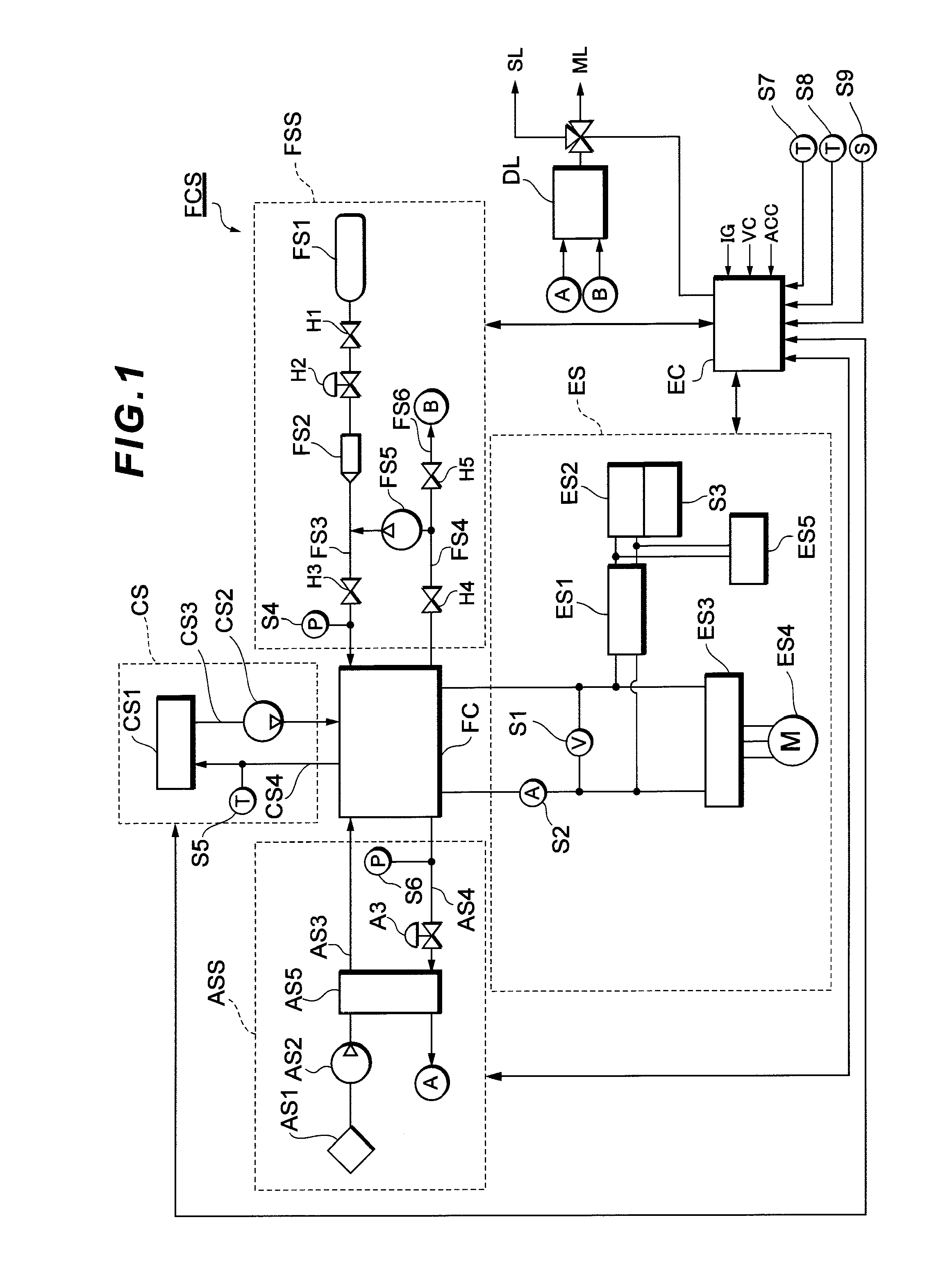
[0022]Firstly, a fuel cell system FCS mounted in a fuel cell vehicle which is the embodiment of the present invention will be described with reference to FIG. 1. FIG. 1 is a diagram showing a system configuration of a fuel cell system FCS which serves as an on-vehicle power source system of a fuel cell vehicle. The fuel cell system FCS can be mounted in vehicles such as fuel cell hybrid vehicles (FCHV), electric vehicles and hybrid vehicles.

[0023]The fuel cell system FCS comprises a fuel cell FC, an oxidant gas supply system ASS, a fuel gas supply system FSS, an electric power system ES, a cooling system CS and a controller EC. The fuel cell FC is supplied with a reactant gas...


PUM


Abstract

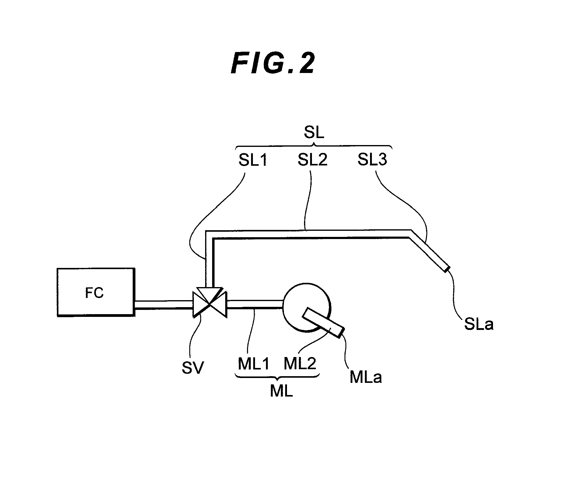
This fuel cell system is for suppressing a backflow of water from an exhaust pipe outlet that discharges a reactant-off gas, without decreasing the performance and fuel consumption of a fuel cell, the exhaust pipe being configured to switch between a main discharge pipe and a sub discharge pipe by a switching means to discharge the reactant-off gas. The sub discharge pipe includes a rising gradient portion formed to incline upwards above a gradient of the main discharge pipe and a falling gradient portion formed to incline downwards at the downstream of the rising gradient portion. The switching valve switches to allow the reactant-off gas to be discharged from the main discharge pipe if an amount of reactant-off gas to be discharged is equal to or above a threshold value of an amount of discharge, and allow the reactant-off gas to be discharged from the sub discharge pipe if the amount of reactant-off gas to be discharged is below the threshold value of the amount of discharge.

Description

TECHNICAL FIELD[0001]The present invention relates to a fuel cell system.BACKGROUND ART[0002]In a fuel cell system, an oxidant gas (e.g., air) and a fuel gas (e.g., hydrogen) are supplied to a fuel cell, and electric power is generated through an electrochemical reaction of these reactant gases. Water that is generated in the fuel cell caused by this electrochemical reaction is discharged to the outside through an exhaust system of the fuel cell while the fuel cell system is in operation. However, when the outside-air temperature is low, the moisture inside the exhaust system freezes, and it may not be possible to continue the operation or restart the operation once it has been stopped. In order to solve such a problem, in the Patent Document 1 below, two exhaust systems with paths of small cross-sectional areas are provided such that it is possible to continue or restart the operation by ensuring an exhaust path in one of the exhaust systems even if the other one of the exhaust sys...

Claims


Application Information

Patent Timeline
IPC IPC(8): H01M8/04
CPCY02E60/50H01M8/04291H01M8/04B60L50/50
Inventor SUEMATSU, KEIGOISHIKAWA, TOMOTAKASAKAJO, YUICHI
Owner TOYOTA JIDOSHA KK
Learn More