
Printing apparatus and electronic device

a printing apparatus and electronic device technology, applied in the direction of printing, digital output to print units, instruments, etc., can solve the problems of increasing the circuit scale, the operation error of the apparatus, and the instability of the output of the low voltage differential buffer, so as to reduce the circuit scale of the head substrate.

Inactive Publication Date: 2012-08-23
CANON KK
View PDF1 Cites 5 Cited by
  • Summary
  • Abstract
  • Description
  • Claims
  • Application Information

AI Technical Summary

Benefits of technology

The invention allows for controlling when an electronic device turns off without requiring extra components or taking up space on its printed circuit board. This results in fewer connections needed between the printing machine and the device, making it more efficient and compact.

Problems solved by technology

The technical problem addressed in this patent relates to instability caused by improper control of signals during data transfer between components within a device employing low voltage differential signaling. In particular, it discusses issues related to the use of a power-down terminal and the importance of controlling both the power-down and reset signals when utilizing a delay circuit to address potential errors resulting from unstable power-down outputs.

Method used


Image

  • Printing apparatus and electronic device
  • Printing apparatus and electronic device
  • Printing apparatus and electronic device

Examples


Embodiment Construction

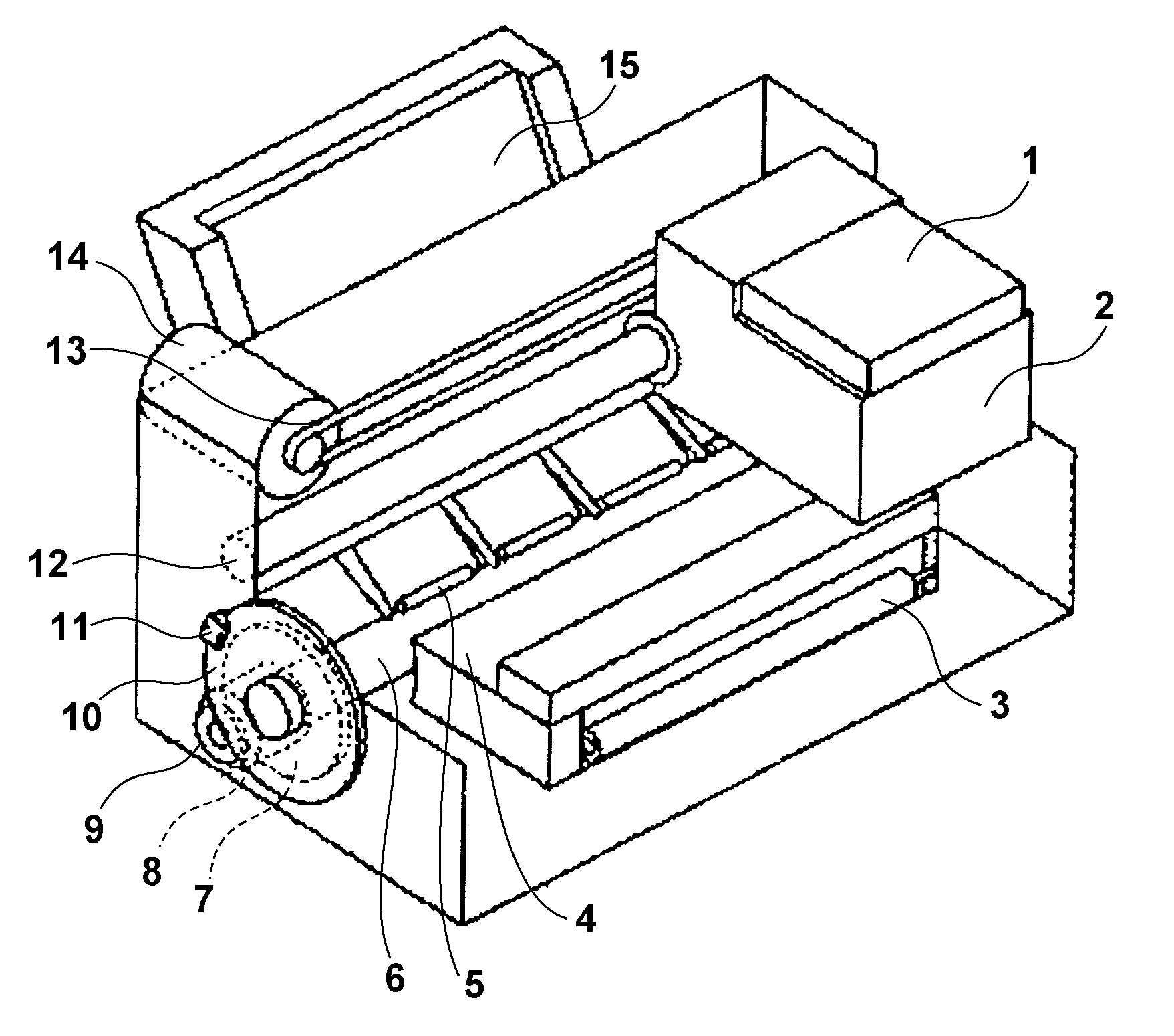
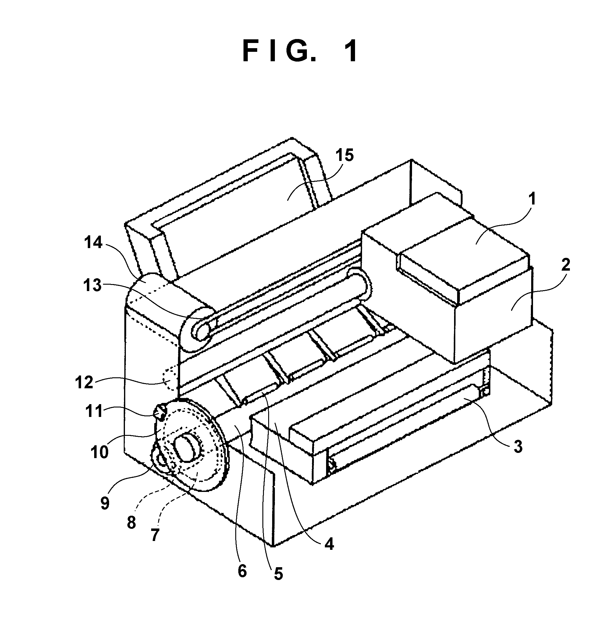
[0020]An exemplary embodiment of the present invention will now be described in detail in accordance with the accompanying drawings. Note that an arrangement to be disclosed in the following embodiment is merely illustrative, and the present invention is not limited to the illustrated arrangement. The present invention is applied to even another electronic device.

[0021]In this specification, the terms “print” and “printing” not only include the formation of significant information such as characters and graphics, but also broadly includes the formation of images, figures, patterns, and the like on a print medium, or the processing of the medium, regardless of whether they are significant or insignificant and whether they are so visualized as to be visually perceivable by humans.

[0022]Also, the term “print medium” not only includes a paper sheet used in common printing apparatuses, but also broadly includes materials, such as cloth, a plastic film, a metal plate, glass, ceramics, woo...


PUM


Abstract

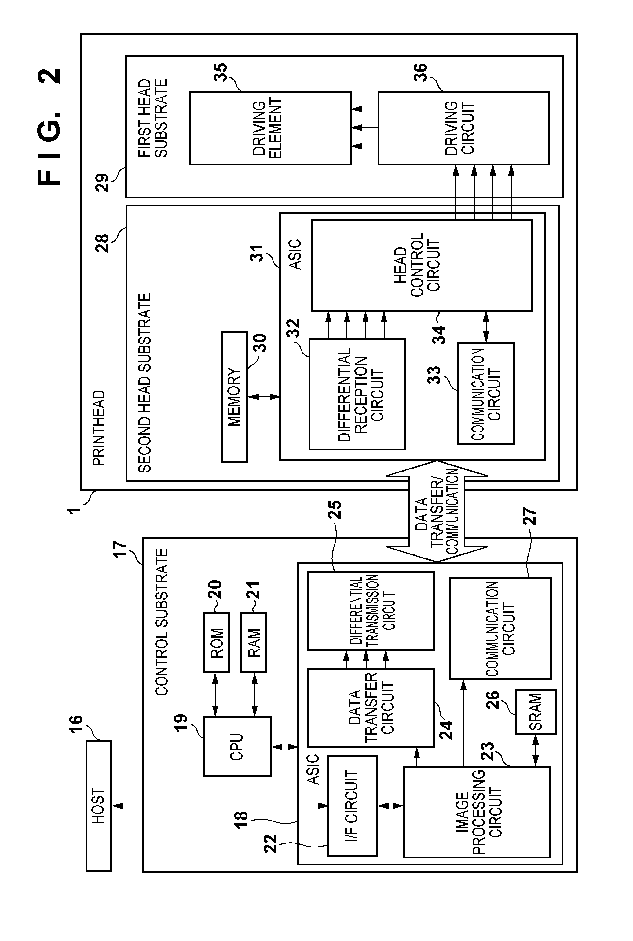
In serial data transfer using an LVDS, when the power-down signal of a low voltage differential buffer is controlled using a clock signal used for the transfer as the operation clock of a reception side circuit, the power-down signal and reset signal need to be controlled properly; otherwise, an apparatus operation may become unstable due to an unstable clock signal. To solve this problem, the power-down signal of the low voltage differential buffer is controlled in consideration of the logical condition for a reset signal for the ASIC of a printhead and a communication signal. The clock signal can be supplied into the printhead to de-assert reset of the ASIC without using any dedicated control signal and delay circuit at the timing when an output from the low voltage differential buffer stabilizes.

Description


Claims


Application Information

Patent Timeline
Owner CANON KK
Learn More