
Interceptor projectile and method of use

a technology of interceptor and projectile, applied in the field of devices and methods for defending against incoming projectiles, can solve the problem of incoming projectiles missing their intended targets

Active Publication Date: 2012-08-23
RAYTHEON CO
View PDF50 Cites 49 Cited by
  • Summary
  • Abstract
  • Description
  • Claims
  • Application Information

AI Technical Summary

Benefits of technology

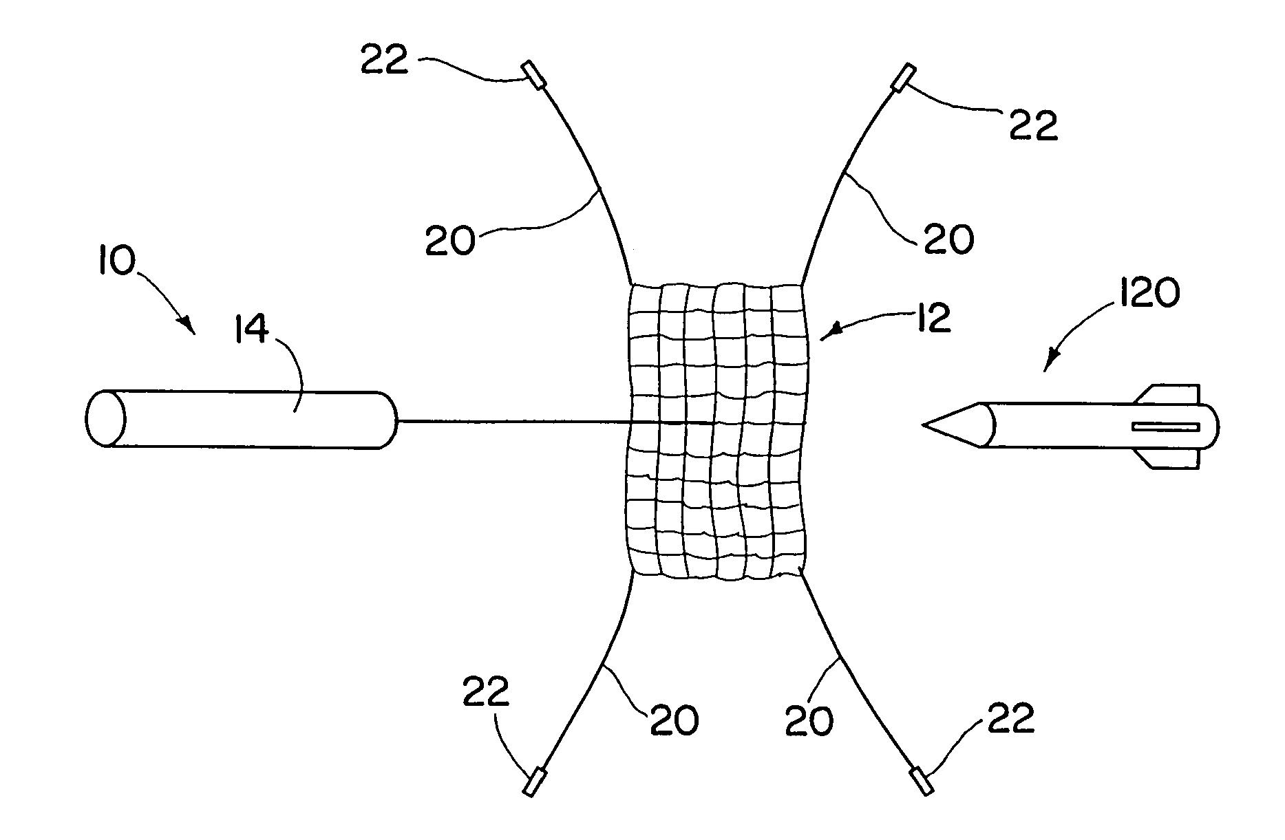
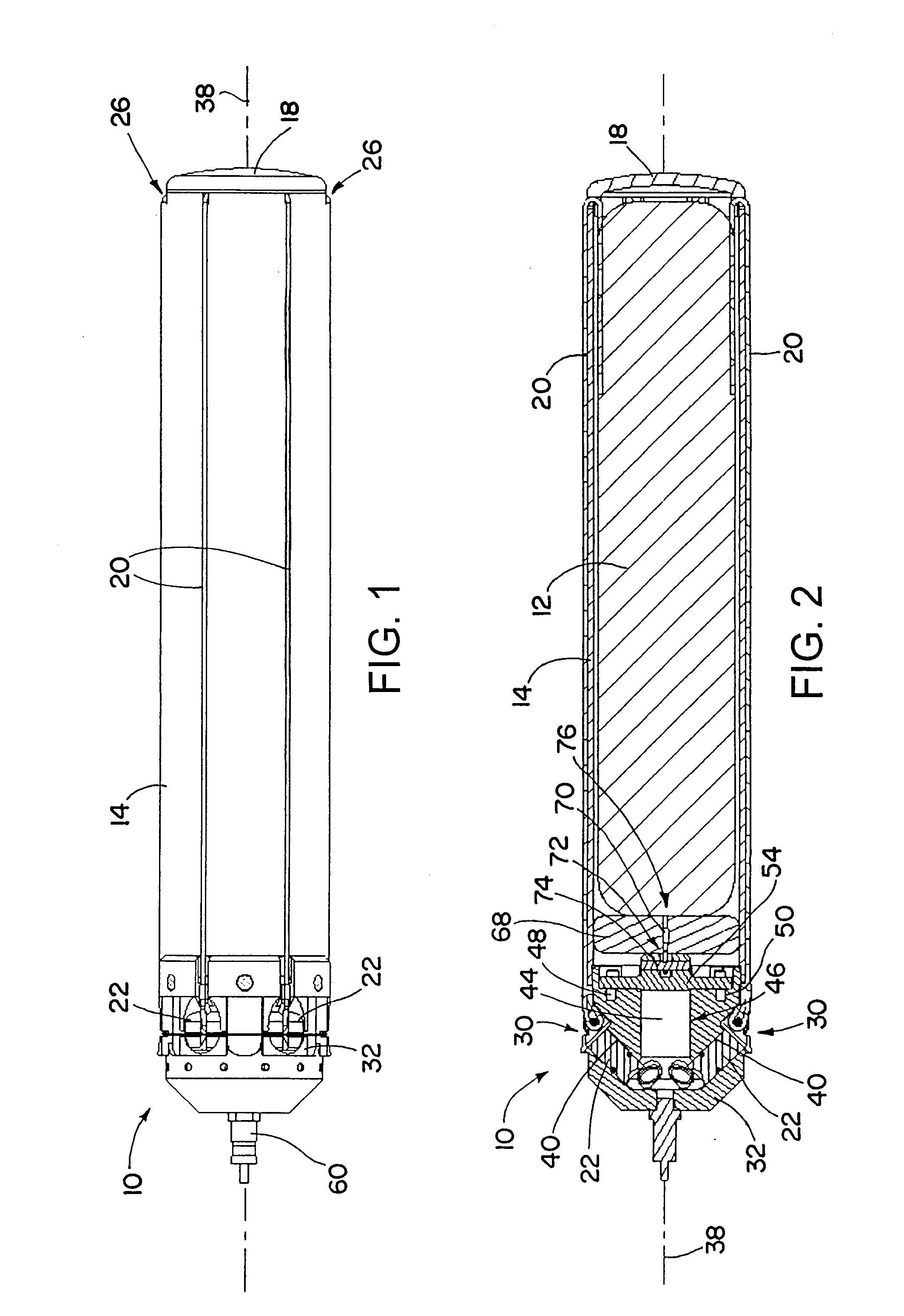
[0005]A weapons interceptor projectile includes a deployable net that wraps around and disables an incoming projectile. Metal weights are attached to ends of the net via metal cable lanyards. The metal weights are fired off from the projectile with a radial component of velocity. The net is also actively propelled with an explosive device. The weights aid in deploying the net quickly to its maximum area, and rotate around the center of the net during flight, aiding in wrapping the net around an incoming projectile. Substantially all of the device remains connected together, even after deployment. The net ensnares and disables the incoming projectile, causing the incoming projectile to miss its intended target. The interceptor projectile solves the fragmentation problem encountered by projectiles using warheads. In addition, ensnaring an incoming projectile using a net may advantageously allow capture and recovery of an enemy projectile.
[0009]According to a further aspect of the invention, a weapon interceptor projectile has a deployable net and weights that are attached to the end of the net. The weights are initially located aft of the net, and rotate about a center of the net during the deployment process. The weights may aid in wrapping the net around an incoming projectile after the incoming projectile has made contact with the net.

Problems solved by technology

The net ensnares and disables the incoming projectile, causing the incoming projectile to miss its intended target.

Method used


Image

  • Interceptor projectile and method of use
  • Interceptor projectile and method of use
  • Interceptor projectile and method of use

Examples


Embodiment Construction

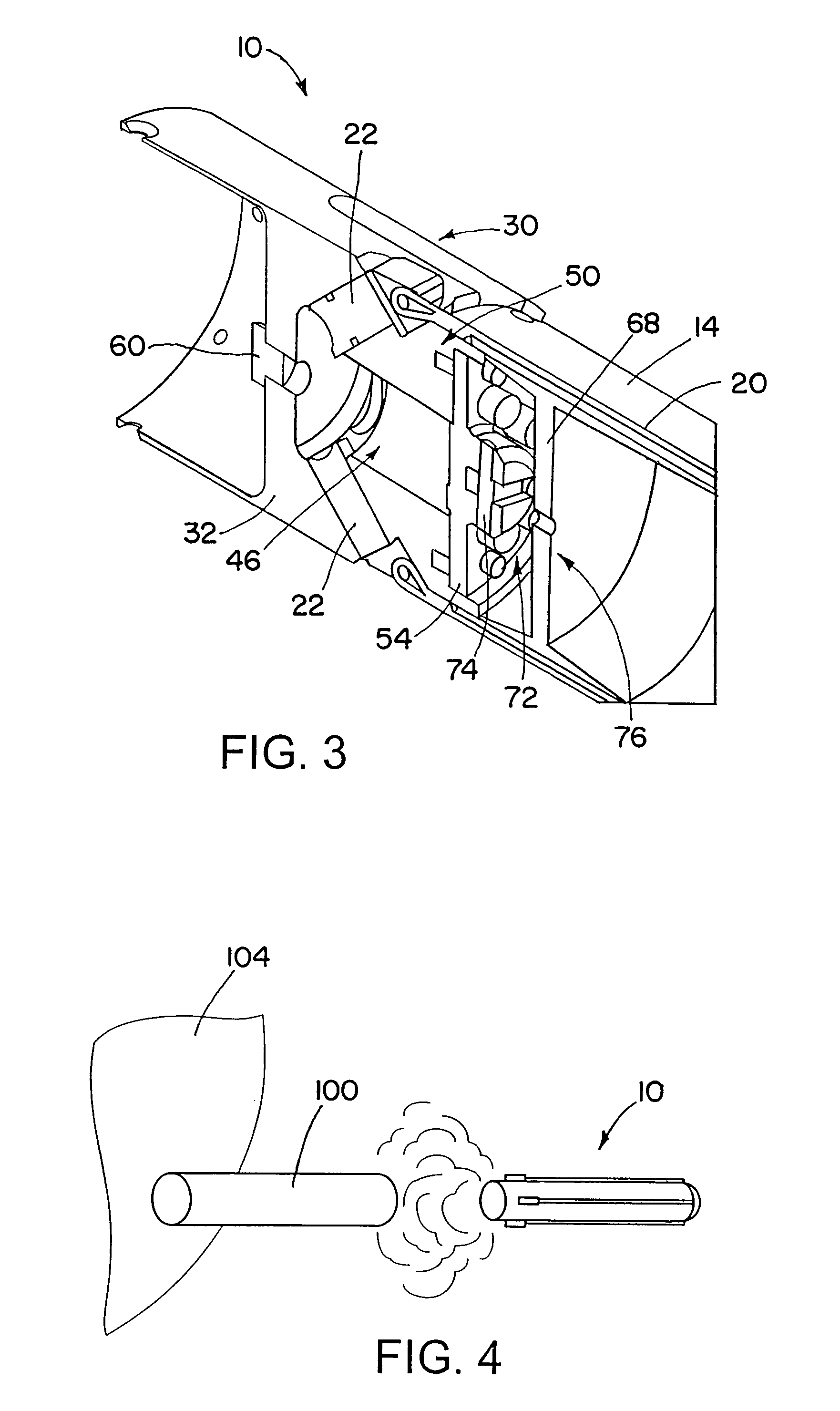
[0024]An interceptor projectile includes a deployable net that deploys during flight and wraps around an incoming projectile, such as a rocket propelled grenade (RPG). The net is initially in a tubular body of the interceptor projectile. Weights are attached to ends of the net with metal cables. A propellant is used to deploy the net from the tubular body and to deploy the weights at acute angles to the longitudinal axis of the interceptor projectile. Separate propellant charges, in separate chambers that are in communication with one another, are used to propel both the weights and the net. A net piston is also propelled forward with the net. The weights move radially out from the interceptor projectile, expanding the net outward, and wrapping the net around an incoming projectile. The engagement of the net with the incoming projectile disables the incoming projectile, sending the incoming projectile off course. This successfully defends a target against the incoming projectile. Th...


PUM


Abstract

An interceptor projectile includes a deployable net that deploys during flight and wraps around an incoming projectile, such as a rocket propelled grenade (RPG). The net is initially in a tubular body of the interceptor projectile. Weights are attached to ends of the net with metal cables. A propellant is used to deploy the net from the tubular body and to deploy the weights at acute angles to the longitudinal axis of the interceptor projectile. The weights move radially out from the interceptor projectile, expanding the net outward, and wrapping the net around an incoming projectile. The engagement of the net with the incoming projectile disables the incoming projectile, sending the incoming projectile off course.

Description

BACKGROUND OF THE INVENTION[0001]1. Technical Field of the Invention[0002]The invention is in the field of devices and methods for defending against incoming projectiles.[0003]2. Description of the Related Art[0004]Rocket propelled grenades (RPGs) are examples of a type of projectile that poses a great threat to ground vehicles and helicopters. RPGs are commonly used during close-in military engagements, where the shooter and the target are close to one another. Defeating an incoming RPG with a fragmentation warhead interceptor may destroy the incoming RPG, but may also in the process produce a shower of fragments. These fragments may injure personnel or cause damage, such as by causing damage to a helicopter that is being fired upon. From the foregoing it will be appreciated that it may be desirable to have improved ways of dealing with incoming projectiles.SUMMARY OF THE INVENTION[0005]A weapons interceptor projectile includes a deployable net that wraps around and disables an inc...

Claims


Application Information

Patent Timeline
IPC IPC(8): F42B12/68
CPCF41H11/02F42B12/68F42B12/56F41H13/0006
Inventor MEREMS, PAUL A.
Owner RAYTHEON CO
Learn More