Motion path search device and method of searching for motion path
- Summary
- Abstract
- Description
- Claims
- Application Information
AI Technical Summary
Benefits of technology
Problems solved by technology
Method used
Image
Examples
embodiment 1
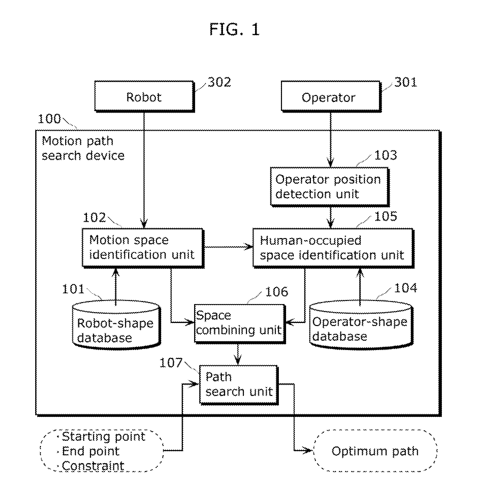
[0081]FIG. 1 is a block diagram showing a basic functional configuration of a motion path search device 100 in Embodiment 1. As shown in FIG. 1, the motion path search device 100 includes a robot-shape database 101, a motion space identification unit 102, an operator position detection unit 103, an operator-shape database 104, a human-occupied space identification unit 105, a space combining unit 106, and a path search unit 107.
[0082]The robot-shape database 101 stores robot-shape data indicating the shape of a robot 302 which performs automated operation.
[0083]The motion space identification unit 102 corresponds to a first space identification unit. The motion space identification unit 102 identifies a space swept through by movable parts of the robot 302 in direct teaching.
[0084]Specifically, the motion space identification unit 102 identifies a space swept through by the movable parts of the robot 302 in direct teaching by determining spaces occupied by the robot 302 at points of...
embodiment 2
[0146]Embodiment 2 shall be described below with reference to the drawings. The description of the part in common with Embodiment 1 will not be repeated herein.
[0147]FIG. 16 is a block diagram showing a basic functional configuration of the motion path search device 100 in Embodiment 2. As shown in FIG. 16, the motion path search device 100 in Embodiment 2 includes an operator-shape obtainment unit 1701 in addition to the components included in the motion path search device in Embodiment 1.
[0148]The operator-shape obtainment unit 1701 changes operator-shape data stored in the operator-shape database 104 according to an input of a position of the operator detected by the operator position detection unit 103.
[0149]The operator-shape database 104 stores operator-shape data indicating the shape of a forearm of the operator 301. For example, the operator-shape data indicates a cylindrical shape 1801 as shown in FIG. 17. The size of the cylindrical shape 1801 is defined by two numerical p...
embodiment 3
[0154]Embodiment 3 shall be described below with reference to the drawings. The description of the part in common with Embodiment 1 will not be repeated herein.
[0155]FIG. 18 is a block diagram showing a basic functional configuration of the motion path search device 100 in Embodiment 3. As shown in FIG. 18, the motion path search device 100 in Embodiment 3 includes an operator-shape determination unit 1901 in addition to the components included in the motion path search device in Embodiment 1.
[0156]The operator-shape determination unit 1901 determines whether the operator 301 is teaching an operation to the robot 302 with his or her right arm, the left arm, or both arms, by using, as an input, the position of the operator 301 detected by the operator position detection unit 103, the posture of the robot 302 output by the motion space identification unit 102, and operator-shape data stored in the operator-shape database 104. Then, the operator-shape determination unit 1901 outputs th...
PUM
 Abstract
Description
Claims
Application Information
 - R&D
- Intellectual Property
- Life Sciences
- Materials
- Tech Scout
- Unparalleled Data Quality
- Higher Quality Content
- 60% Fewer Hallucinations
Browse by: Latest US Patents, China's latest patents, Technical Efficacy Thesaurus, Application Domain, Technology Topic, Popular Technical Reports.
© 2025 PatSnap. All rights reserved.Legal|Privacy policy|Modern Slavery Act Transparency Statement|Sitemap|About US| Contact US: help@patsnap.com


