Electronic device, pedometer, and program

a technology of pedometer and electronic device, applied in the field of electronic device, pedometer, and program, can solve the problems of inability to distinguish between, affecting the operation of the switch, and becoming more difficult to provide both the visibility of the display section and the operability of the switch,

Inactive Publication Date: 2012-08-09
SEIKO INSTR INC
View PDF2 Cites 6 Cited by
  • Summary
  • Abstract
  • Description
  • Claims
  • Application Information

AI Technical Summary

Benefits of technology

[0018]According to the present application, the input of the switch based on an acceleration signal from the user during walking can be performed reliably.

Problems solved by technology

As the pedometer of this type is reduced in size, it is becoming more difficult to provide both of visibility of a display section and operability of switches.
In the portable electronic device described in Patent Document 1, however, it is impossible to distinguish between acceleration produced in the electronic device due to walking or running and acceleration produced in the electronic device due to the predetermined motion, so that the predetermined operation may not be performed.
Thus, the portable electronic device described in Patent Document 1 has a drawback in that it may not operate in accordance with the motion of a user while the user walks or runs.

Method used


Image

  • Electronic device, pedometer, and program
  • Electronic device, pedometer, and program
  • Electronic device, pedometer, and program

Examples


Embodiment Construction

[0026]An embodiment of the present invention will hereinafter be described in detail with reference to the drawings. In the present embodiment, description is made with an example of a pedometer, as an exemplary acceleration detector.

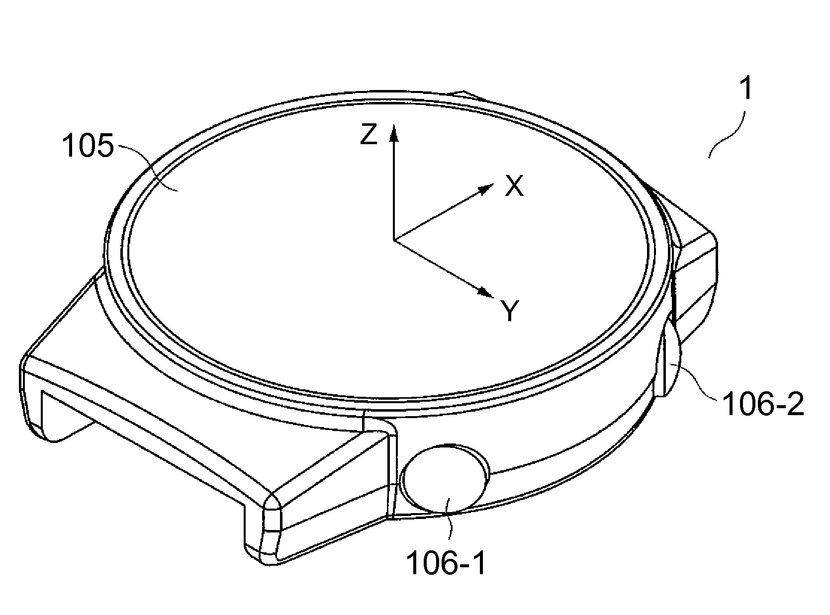
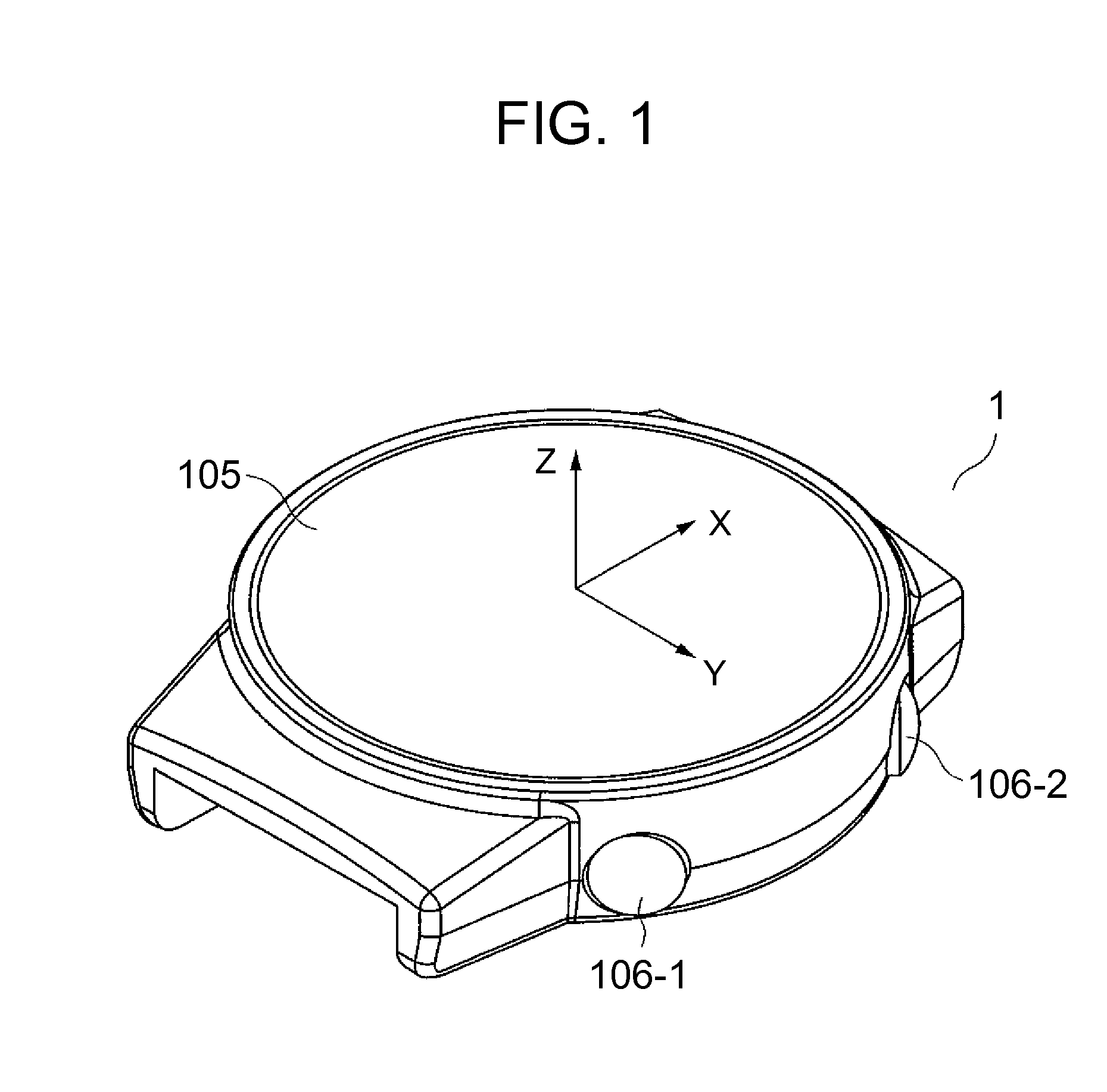
[0027]FIG. 1 is an external view showing the outer appearance of the pedometer. In the example shown, the pedometer 1 includes a display section 105 on an upper face, and input sections 106-1 and 106-2 (mechanical switches) on a side face.

[0028]The display section 105 includes a display face to display the number of steps and the time measured by a stopwatch function.

[0029]The input switches 106-1 and 106-2 receive input of an instruction from a user to start or stop the pedometer or to store a lap time in a stopwatch mode.

[0030]The same plane as the display face of the display section 105 is defined as an XY plane, a direction of 6-to-0 o'clock is defined as an X axis, and a direction of 9-to-3 o'clock is defined as Y axis. A direction perpendicular to...


PUM


Abstract

To allow reliable input of a switch based on an acceleration signal from a user during walking. An electronic device includes a display section displaying information on a display section, a first acceleration sensor detecting acceleration in a direction perpendicular to the display face, and an input detection section detecting input based on the acceleration detected by the first acceleration sensor.

Description

FIELD OF THE INVENTION[0001]The present invention relates to an electronic device, a pedometer, and a program.BACKGROUND ART[0002]A wristwatch-type pedometer for counting the number of steps based on an acceleration signal has conventionally been known. As the pedometer of this type is reduced in size, it is becoming more difficult to provide both of visibility of a display section and operability of switches.[0003]Patent Document 1 (JP-A-2008-33526) has described a portable electronic device which achieves control such that predetermined computations are performed on the basis of acceleration detected by the portable electronic device to produce an evaluation signal indicating the amplitude and the positive / negative polarity of the acceleration, it is determined on the basis of the evaluation signal whether or not the portable electronic device is subjected to a predetermined motion, and a predefined operation is performed on the basis of the determination result.[0004]In the porta...

Claims


Application Information

Patent Timeline
Patent Type & Authority Applications(United States)
IPC IPC(8): G01C22/00
CPCG04G21/02G01C22/006
Inventor NAKAMURA, HISAO
Owner SEIKO INSTR INC
Why Eureka
Try Eureka