
Method, Apparatus and Computer Program for Processing Multi-Channel Signals

a multi-channel audio and audio signal technology, applied in the field of multi-channel audio signal processing methods, apparatuses and computer program products, can solve the problems of reducing the quality of reconstructed signals, reducing the amount of ambience or spaciousness of reconstructed signals, and typically computationally complex models

Active Publication Date: 2012-08-02
NOKIA TECHNOLOGLES OY
View PDF6 Cites 4 Cited by
  • Summary
  • Abstract
  • Description
  • Claims
  • Application Information

AI Technical Summary

Benefits of technology

[0014]According to some example embodiments of the present invention a high number of input channels can be provided to an end user at a high quality at reduced bit-rate. When applied to a multi-view audio application, it enables the end user to select different aural views from audio scene that contains multiple aural views to the audio scene in storage / transmission efficient manner.
[0016]Some example embodiments of the present invention allow creating a sparse representation for the multi-channel signals. The sparse representation itself is a very attractive property in any signal to be coded as it translates directly to a number of frequency domain samples that need to be coded. In sparse representation (of a signal) the number of frequency domain samples, also called frequency bins, may be greatly reduced which has direct implications to the coding approach: data rate may be significantly reduced with no quality degradation or quality significantly improved with no increase in the data rate.

Problems solved by technology

Furthermore, a similar challenge regarding the required transmission bandwidth is naturally valid also for any multi-channel audio signal.
These models are typically computationally quite complex even with single channel signals not to mention multi-channel signals with relatively high number of input channels.
While efficient in bitrate, these methods typically lack in the amount of ambience or spaciousness in the reconstructed signal.

Method used


Image

  • Method, Apparatus and Computer Program for Processing Multi-Channel Signals
  • Method, Apparatus and Computer Program for Processing Multi-Channel Signals
  • Method, Apparatus and Computer Program for Processing Multi-Channel Signals

Examples


Embodiment Construction

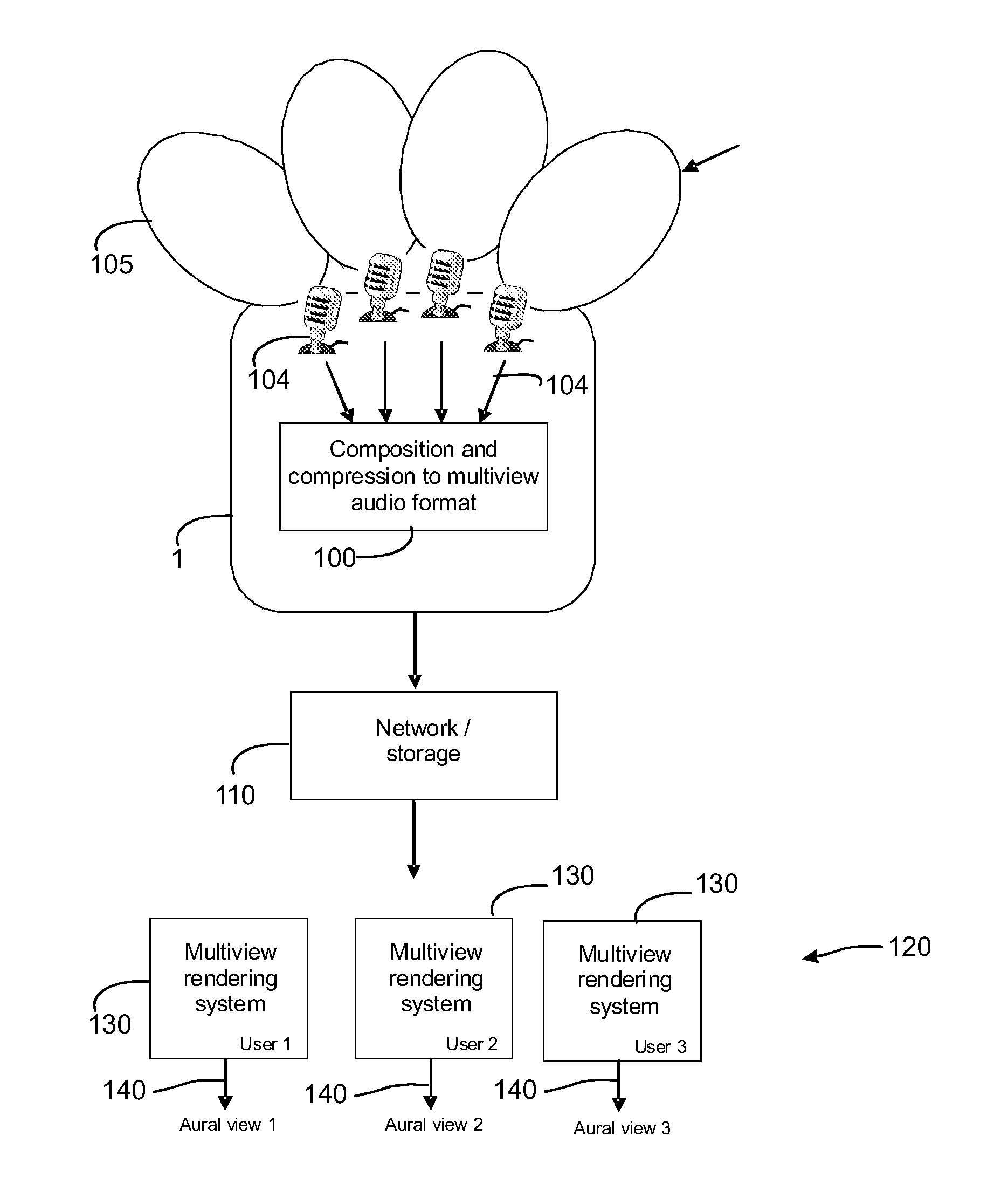
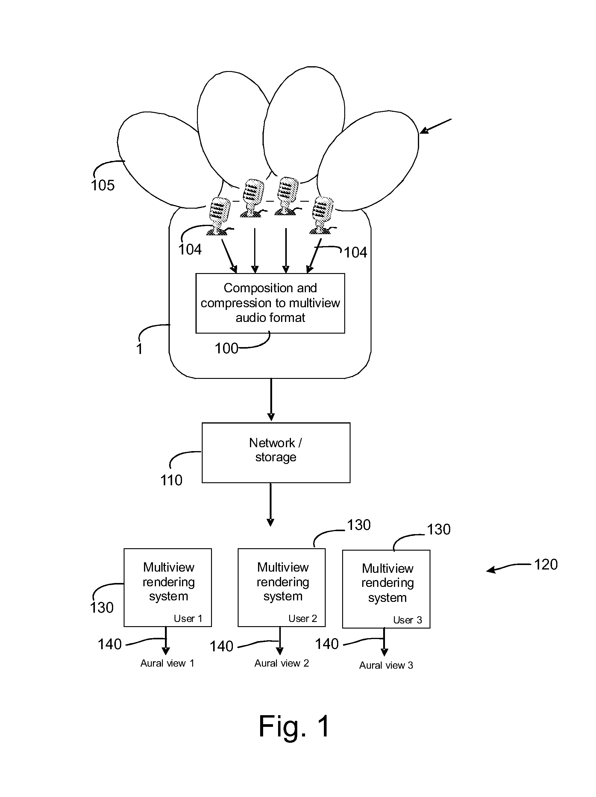
[0054]In the following an example embodiment of the apparatuses for encoding and decoding multi-view audio signals by utilising the present invention will be described. An example of a multi-view audio capture and rendering system is illustrated in FIG. 1. In this example framework set-up, multiple, closely spaced microphones 104, all possibly pointing toward different angle relative to the forward axis, are used to record an audio scene by an apparatus 1. The microphones 104 have a polar pattern which illustrates the sensitivity of the microphone 104 to convert audio signals into electrical signals. The spheres 105 in FIG. 1 are only illustrative, non-limiting examples of the polar patterns of the microphones. The captured signals which are composed and compressed 100 to a multi-view format, are then transmitted 110 e.g. via a communication network to a rendering side 120, or alternatively stored into a storage device for subsequent consumption or for subsequent delivery to another...


PUM


Abstract

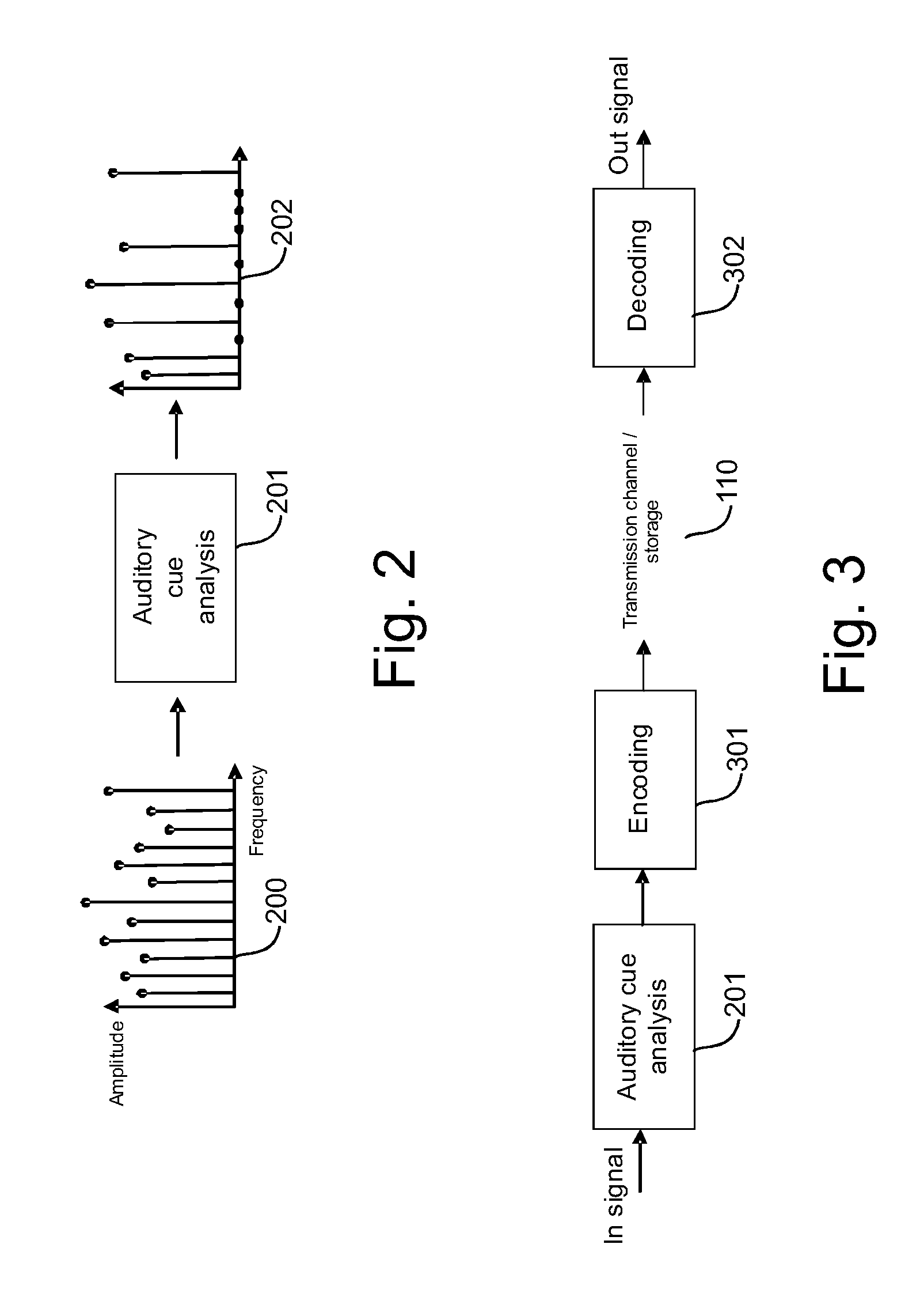
The invention relates to a method and an apparatus in which samples of at least a part of an audio signal of a first channel and a part of an audio signal of a second channel are used to produce a sparse representation of the audio signals to increase the encoding efficiency. In an example embodiment one or more audio signals are input and relevant auditory cues are determined in a time-frequency plane. The relevant auditory cues are combined to form an auditory neurons map. Said one or more audio signals are transformed into a transform domain and the auditory neurons map is used to form a sparse representation of said one or more audio signal.

Description

TECHNICAL FIELD[0001]The present invention relates to a method, an apparatus and a computer program product relating to processing multi-channel audio signals.BACKGROUND INFORMATION[0002]Spatial audio scene consists of audio sources and ambience around a listener. The ambience component of a spatial audio scene may comprise ambient background noise caused by the room effect, i.e. the reverberation of the audio sources due to the properties of the space the audio sources are located, and / or other ambient sound source(s) within and / or the auditory space. The auditory image is perceived due to the directions of arrival of sound from the audio sources as well as the reverberation. A human being is able to capture the three dimensional image using signals from the left and the right ear. Hence, recording the audio image using microphones placed close to ear drums is sufficient to capture the spatial audio image.[0003]In stereo coding of audio signals two audio channels are encoded. In ma...

Claims


Application Information

Patent Timeline
Patent Type & Authority Applications(United States)
IPC IPC(8): H04R5/00G10L19/00G10L19/008G10L19/02G10L19/022
CPCG10L19/008G10L19/0212H04S2400/15H04S3/008G10L19/022
Inventor OJANPERA, JUHA
Owner NOKIA TECHNOLOGLES OY
Learn More