
Motor vehicle structure, and method of making a motor vehicle structure

a technology of motor vehicles and composite materials, applied in the direction of vehicle bodies, superstructure subunits, monocoque constructions, etc., can solve the problems of cumbersome cleaning and/or preparation processes, adversely affecting the cycle time of the production process, and the inability to manufacture hybrid structures, etc., to achieve better flow characteristics of matrix resin and prevent smudging of matrix resin before or during molding

Active Publication Date: 2012-08-02
SGL CARBON SE
View PDF4 Cites 7 Cited by
  • Summary
  • Abstract
  • Description
  • Claims
  • Application Information

AI Technical Summary

Benefits of technology

[0013]Overall, the present invention provides a structural union which is predominantly elastically deformed in the event of a crash without adversely affecting the bond and without breaking or splintering the reinforcement element. As a result, the crash performance is maintained and the components can be dimensioned to lower their overall weight as they undergo predominantly an elastic deformation.
[0032]According to another advantageous feature of the present invention, the motor vehicle structure may be subjected to a local heat treatment during or after the production process. Local heat treatment results in the realization of particular properties of the matrix resin and curing of the matrix resin. For example, it may be suitable to provide better flow characteristics of the matrix resin in certain regions of the base body through pre-heating. Moreover, local heat treatment during or after the production method allows realization of different hardness degrees of the joint being produced. Especially when considering the realized properties of the reinforcement of the motor vehicle structure in accordance with the production method of the present invention, there are many benefits, also when taking into account the absence of any fiber breakage.

Problems solved by technology

Manufacture of hybrid structures is fairly complex because the individual components must be produced and then connected to one another.
In particular when using fiber composites, curing times and bonding times have to be taken into account and adversely affect the cycle time of the production process.
Moreover, cumbersome cleaning and / or preparation processes are necessary for coupling metallic components with fiber composites.
A drawback of conventional coupling processes for manufacturing hybrid structures resides in the absence of maintaining an even joining gap when for example bonding or foaming the components to be connected.
In addition, structural tolerances between the components adversely affect the connection as the attachments are inadequate and gaps can form between the components.
This can lead to corrosion when used in the manufacture of a vehicle body part and thus adversely affect crash performance when a force level is exceeded.

Method used


Image

  • Motor vehicle structure, and method of making a motor vehicle structure
  • Motor vehicle structure, and method of making a motor vehicle structure
  • Motor vehicle structure, and method of making a motor vehicle structure

Examples


Embodiment Construction

[0039]Throughout all the figures, same or corresponding elements may generally be indicated by same reference numerals. These depicted embodiments are to be understood as illustrative of the invention and not as limiting in any way. It should also be understood that the figures are not necessarily to scale and that the embodiments are sometimes illustrated by graphic symbols, phantom lines, diagrammatic representations and fragmentary views. In certain instances, details which are not necessary for an understanding of the present invention or which render other details difficult to perceive may have been omitted.

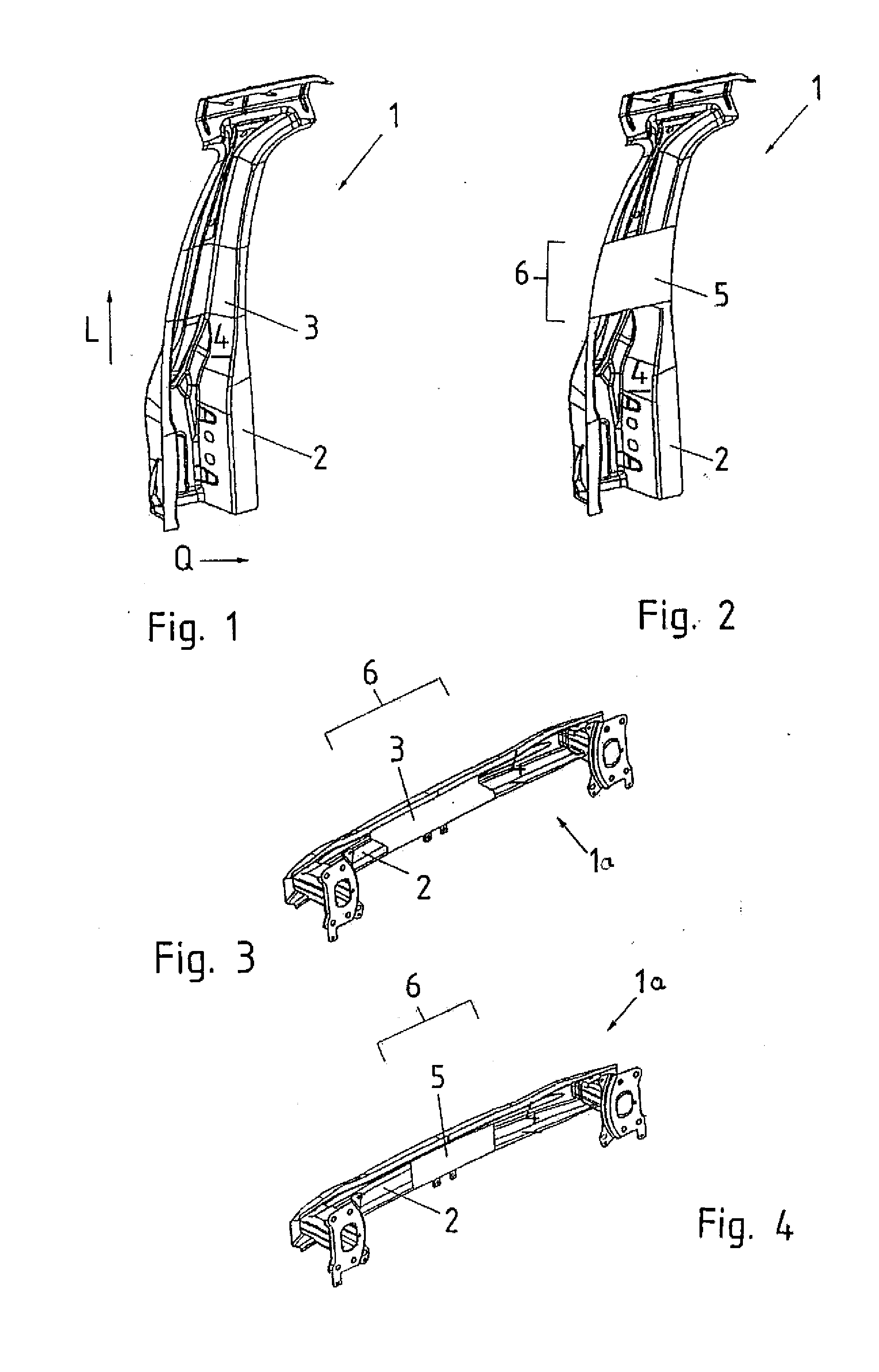
[0040]Turning now to the drawing, and in particular to FIG. 1, there is shown a perspective illustration of one configuration of a motor vehicle structure according to the present invention, generally designated by reference numeral 1 and configured in the form of B-pillar. The motor vehicle structure 1 includes a metallic base body 2 and a reinforcement element 3 applied up...


PUM

PropertyMeasurementUnit
angleaaaaaaaaaa
angleaaaaaaaaaa
thicknessaaaaaaaaaa

Abstract

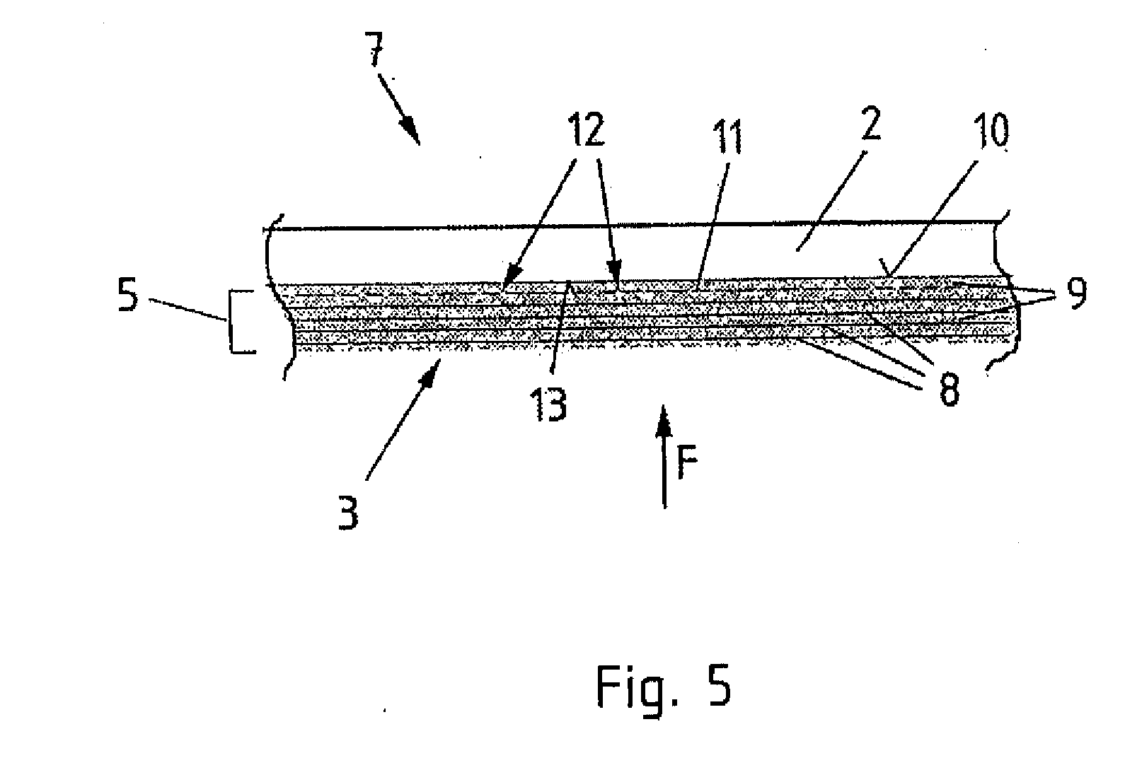
A motor vehicle structure includes a metallic base body in the form of a three-dimensional metal sheet and a reinforcement element made of fiber composite having a matrix resin for coupling the reinforcement element with the base body in a coupling zone by a material joint. Arranged between the base body and the reinforcement element is a non-woven having voids through which the matrix resin is able to permeate.

Description

CROSS-REFERENCES TO RELATED APPLICATIONS[0001]This application claims the priority of German Patent Application, Serial No. 10 2011 009 892.5, filed Jan. 31, 2011, pursuant to 35 U.S.C. 119(a)-(d), the content of which is incorporated herein by reference in its entirety as if fully set forth herein.BACKGROUND OF THE INVENTION[0002]The present invention relates to a motor vehicle structure, and to a method of making a motor vehicle structure.[0003]The following discussion of related art is provided to assist the reader in understanding the advantages of the invention, and is not to be construed as an admission that this related art is prior art to this invention.[0004]It is known to produce body and / or chassis parts in hybrid construction, whereby sections of a metallic base body are reinforced with a fiber-reinforced composite to realize lightweight structures with enhanced crash behavior. Mechanical and bonding processes as well as direct formfitting injection molding have hereby b...

Claims


Application Information

Patent Timeline
Patent Type & Authority Applications(United States)
IPC IPC(8): B62D25/00B29C65/48B29C65/70
CPCB32B15/14Y10T156/1028B62D29/005B32B5/022B32B5/12B32B5/26B32B7/06B32B15/18B32B3/26B32B2260/023B32B2260/046B32B2262/10B32B2262/101B32B2605/00B32B2262/103B32B2262/106B62D25/04
Inventor HOWE, CHRISTIANBÖKE, JOHANNESMACIEJ, MARCO
Owner SGL CARBON SE
Learn More