
System for launching and recovering underwater vehicles, notably towed underwater vehicles

Active Publication Date: 2012-08-02
THALES SA
View PDF19 Cites 13 Cited by
  • Summary
  • Abstract
  • Description
  • Claims
  • Application Information

AI Technical Summary

Benefits of technology

[0016]first drive means for lowering and raising the ramp and hauling means for controlling the sliding of the vehicle along the ramp during the launch and for hoisting the vehicle up along the ramp during recovery, the ramp having an emerged end that occupies a fixed position, this end being able to move only in terms of rotation at least about a horizontal axis perpendicular to the axis of the ship, and a free end the position of which varies, under the action of the first drive means, between an immersed position in which it dips down into the water and an emerged position in which the ramp is in a horizontal position.
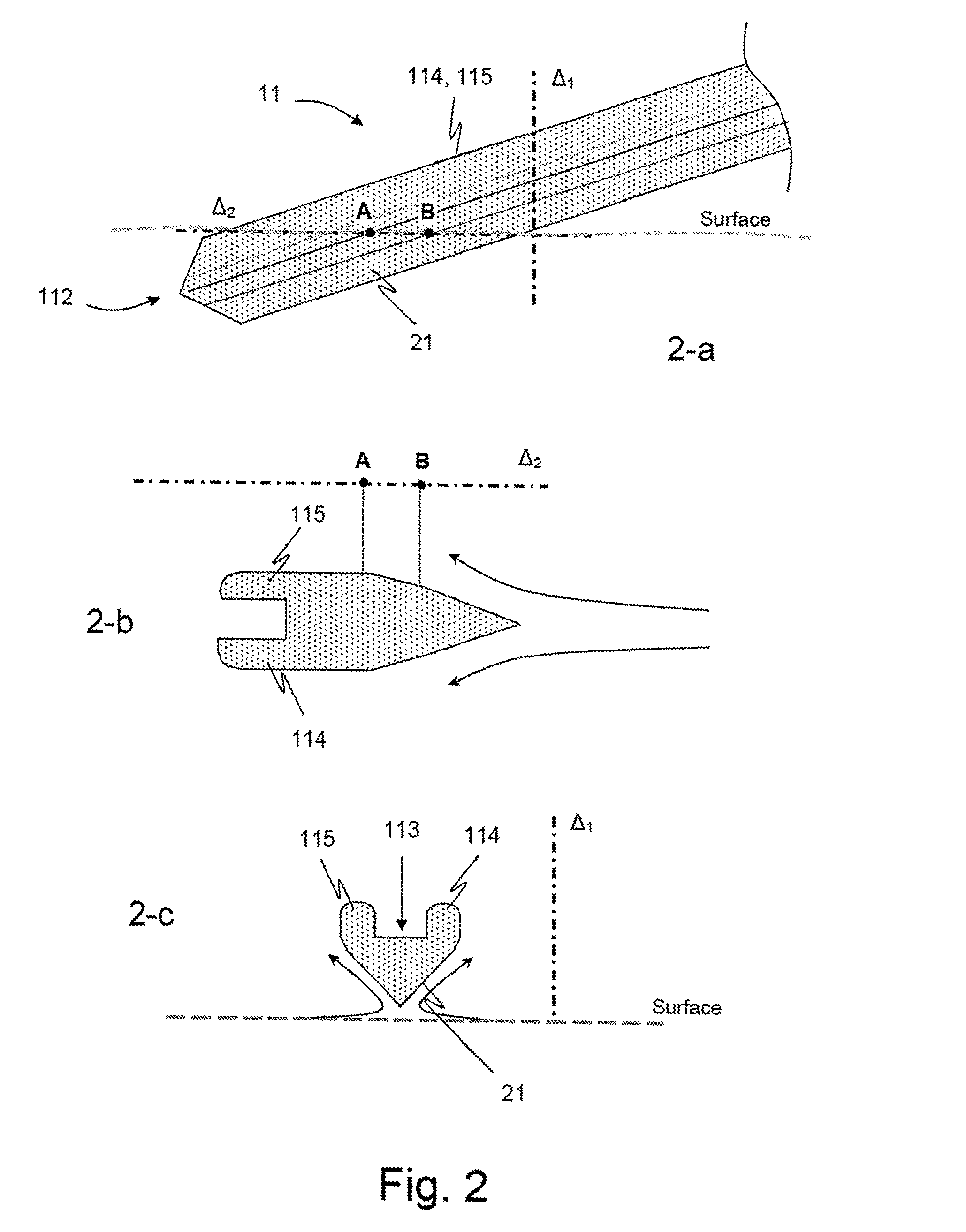
[0018]According to one particular embodiment, the edoes of the ramp are configured so that they, jointly with the streamlining of the lower part of the ramp, provide the free end of the ramp with buoyancy.
[0026]The device according to the invention thus consists of a recovery system that advantageously limits the vertical relative movements between this system and the underwater or marine vehicle when this vehicle is IS floating at the surface, particularly at the critical moment of contact between these two entities during recovery. It allows the vehicle to be launched automatically from its storage position and then allows this vehicle to be recovered following use and returned to its storage position.
[0027]The vertical relative movements are successfully limited by means of an inclinable ramp that is articulated in its upstream part and that in its rear part comprises buoyancy means that allow its free end to float at the surface. Moreover, the streamlined underside of the ramp advantageously limits the impact of the speed of forward travel of the ship and the slamming effects due to the waves an the relative positioning of the rear end of the ramp with respect to the surface of the water, and does so for different sea conditions and different speeds of travel in relation to the water.

Problems solved by technology

This is because it is during these critical phases that the movements of the swell are most dangerous to the integrity of the vehicle, this vehicle being tossed about by the swell while it is in a region on the surface where it is likely violently to strike either the structure of the ship or that of the lifting and handling means.
As a result, launch and lift are performed vertically, thus limiting the possibilities of collision with the ship during lowering or raising.
This type of solution can be applied, notably autonomously, to vehicles towed from the middle but is not, however, readily applicable to the case of vehicles that are towed from the front because, for obvious reasons of efficiency, it is desirable for it to be possible for the vehicle to he towed and handled using the one same cable.
Handling using means such as those described hereinabove using a single cable would prove tricky because it entails the vehicle passing from the vertical position to the horizontal position during launch and vice versa during recovery.
These operations themselves generally require the intervention of human operators, which intervention is made trickier and more hazardous when the sea is rough.
However, such a ramp is generally ill suited to use in heavy seas, because lateral movements of the vehicle could then damage that vehicle.
Specifically, the transition of the vehicle from the surface of the water to the ramp involves the nose of the vehicle coming into contact with the ramp, and this contact, notably when the sea is rough, can be fairly violent and cause damage to the vehicle but also prevent the vehicle from being brought up.
Such solutions nonetheless prove to be insufficient in rough seas, the slamming effect of the waves then being heightened by the movement of the ship.

Method used


Image

  • System for launching and recovering underwater vehicles, notably towed underwater vehicles
  • System for launching and recovering underwater vehicles, notably towed underwater vehicles
  • System for launching and recovering underwater vehicles, notably towed underwater vehicles

Examples


Embodiment Construction

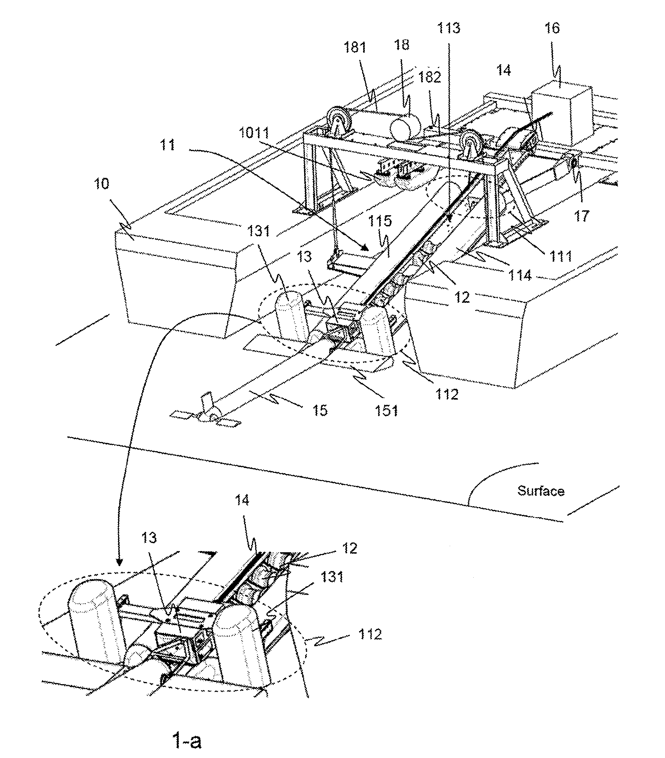
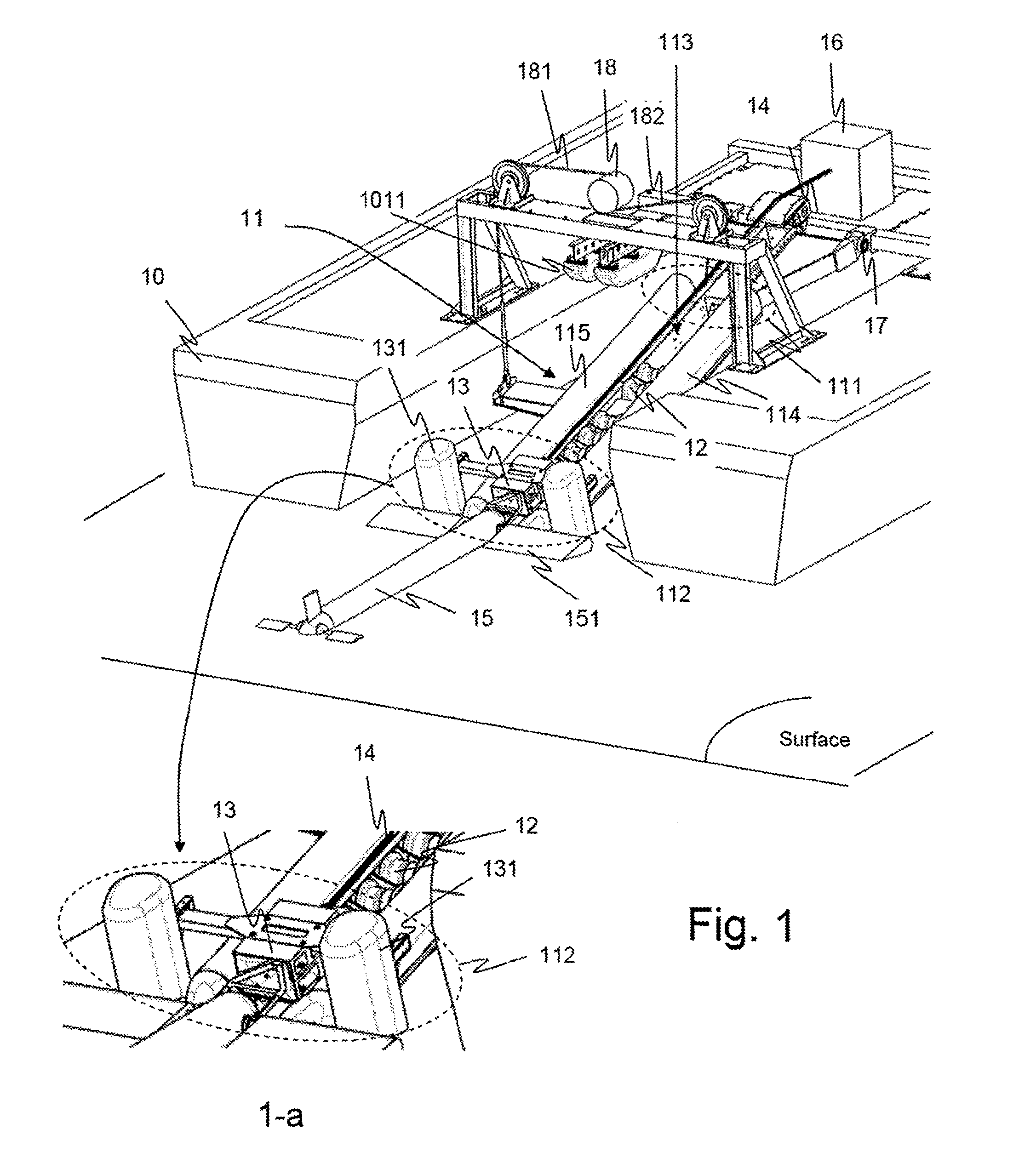
[0033]FIG. 1 gives an overview of this embodiment. In this embodiment, the device is shown on a ship 10 of the catamaran type, between the two hulls thereof. As this figure illustrates, the device according to the invention chiefly comprises the following elements:

[0034]A streamlined articulated ramp 11 preferably situated at the rear of the ship and having one end 111 attached to the ship and one free end 112.

[0035]The fixed end 111 of the ramp is connected to the carrier leaving at least one degree of freedom to rotate about a horizontal axis perpendicular to the main axis of the ramp so that the free end can be raised or lowered in the manner of a drawbridge.

[0036]According to the invention, the ramp 11 is in the overall shape of a chute or channel section with a bottom 113 and edges 114 and 115 the height of which is notably determined according to the size and geometry of the vehicle 15 being handled.

[0037]Means 12 mounted on the ramp and intended to encourage the vehicle to pr...


PUM


Abstract

A system for launching and recovering marine or underwater vehicles from a carrier ship which remains under way which limits the amplitude of pitching and rolling movements. The system includes an inclinable articulated ramp including a bottom and edges, and hauling means for controlling sliding of the vehicle along the ramp during launch and for hoisting the vehicle up along the ramp. The ramp has a free end which varies between an immersed position in the water and an emerged position in a horizontal position. The system also includes buoyancy means allowing the free end of the ramp to float at or near the surface of the water when the ramp is lowered. The bottom of the articulated ramp also has an external face configured to form streamlining thus ensuring fluidity of the end of the ramp in contact with the water and limiting vertical dynamic movements caused by waves.

Description

FIELD OF THE INVENTION[0001]The invention falls within the naval field and relates more specifically to the handling and lifting systems mounted on ships for launching and recovering marine or underwater vehicles from these ships, the vehicles in question being either towed vehicles or self-propelled vehicles, the latter then being fitted with a temporary tether while they are being launched and recovered.PRIOR ART OF THE INVENTION[0002]The operations of launching and recovering a marine or underwater vehicle from a ship which also has the task of transporting this vehicle generally include a phase that is critical, especially in rough seas, which is the transition from the fully emerged state in which the vehicle is secured to the handling means used, to the fully immersed state in which the vehicle has no further contact with these means, and vice versa. This is because it is during these critical phases that the movements of the swell are most dangerous to the integrity of the ve...

Claims


Application Information

Patent Timeline
IPC IPC(8): B63B35/40B63B23/30
CPCB63B23/32B63B27/143B63B2027/165B63C3/02B63B27/36
Inventor SOREAU, DIDIERJEZEQUEL, OLIVIERJOURDAN, MICKAEL
Owner THALES SA
Learn More