
Probe, Diagnosis Device, and Method for Using the Diagnosis Device

a diagnosis device and diagnostic device technology, applied in the field of diagnostic devices and diagnostic devices, can solve the problems of reducing the reliability of diagnosis, difficult to overlap, and large loss of light, and achieve the effect of preferable operability and observation properties, and preferable observation properties

Inactive Publication Date: 2012-07-26
KONICA MINOLTA OPTO
View PDF14 Cites 20 Cited by
  • Summary
  • Abstract
  • Description
  • Claims
  • Application Information

AI Technical Summary

Benefits of technology

[0066]According to the present invention, imaging by the imaging section of the endoscope main body can be performed while illuminating the observation target region with the illuminating section included in the probe and a probe with preferable observation properties can be provided. Specifically, when illumination is provided on the endoscope main body, by turning off the illumination and turning on and off the illuminating section included in the probe, it is possible to switch between an environment suitable for imaging by an endoscope main body and an environment suitable for observation by the probe. Therefore, it is possible to obtain the effect of performing observation in which both preferable operability and observation properties are achieved and being able to use a general endoscope main body including an endoscope channel.

Problems solved by technology

Therefore, it is difficult to overlap the result detected through the probe to a normal image imaged by the endoscope main body.
Therefore, the quantity of light which is lost is large and reliability of diagnosis decreases.
If the quantity of light is increased, there is a concern of bad influence on the human body, and there is a limit with a configuration which uses a single optical path for both transmitting light and receiving light.

Method used


Image

  • Probe, Diagnosis Device, and Method for Using the Diagnosis Device
  • Probe, Diagnosis Device, and Method for Using the Diagnosis Device
  • Probe, Diagnosis Device, and Method for Using the Diagnosis Device

Examples


Embodiment Construction

[0106]An embodiment of the present invention is described below with reference to the drawings. The following is an embodiment of the present invention and does not limit the present invention.

(Example of Entire Configuration)

[0107]The endoscope system of the present embodiment is a fluorescence diagnosis device added to an endoscope.

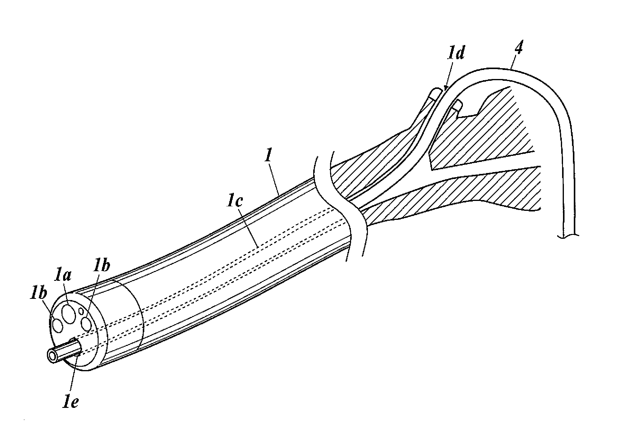
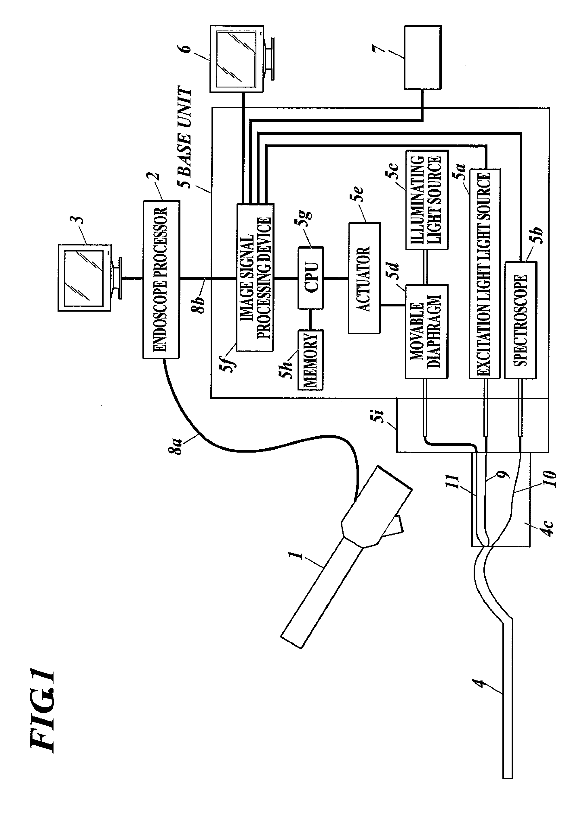
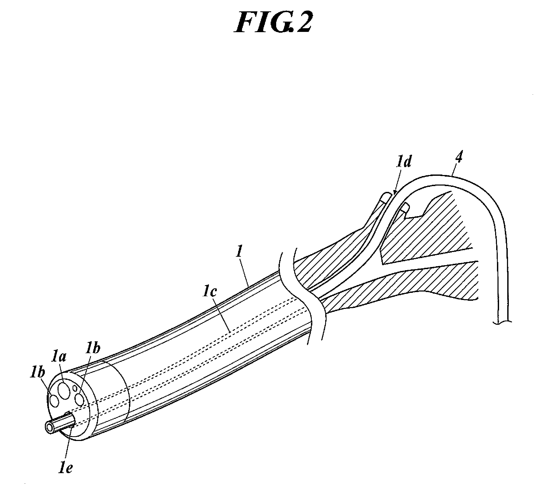
[0108]As shown in FIG. 1, the endoscope system of the present embodiment is configured including an endoscope main body 1, an endoscope processor 2, an endoscope display monitor 3, a probe 4, a base unit 5 of the probe 4, a display monitor 6 which displays an output image of the base unit 5, and an operation input device 7 connected to the base unit 5.

[0109]An electronic camera and illumination is provided on a tip end of the endoscope main body 1. An image signal cable 8a which sends out an image signal imaged by the electronic camera is connected to the endoscope processor 2, and the endoscope processor 2 outputs the image to the endoscope display mon...


PUM


Abstract

A probe (4) is provided with at least a light projecting optical fiber (9) and a light receiving optical fiber (10) and is configured so that excitation light guided by the light projecting optical fiber is applied to the portion of a living organism which is to be observed and then light emitted, due to the excitation light, from the portion to be observed is received by the light receiving optical fiber. The probe (4) is also provided with an illumination means used for the capture of an image by the image capturing means of an endoscope body. The illumination means is, for example, a light emitting diode which is provided to the front end of the probe, a light guiding optical fiber (11) which guides illumination light from an illumination light source (5c) to the front end of the probe, or a light emitting substance piece which is disposed at the front end of the probe and emits white fluorescent light by excitation.

Description

TECHNICAL FIELD[0001]The present invention relates to a probe inserted through an endoscope channel, and a probe which includes an optical system which irradiates irradiated light on an observation target region of biological tissue and which receives emitted light emitted from the observation target region due to the irradiated light.BACKGROUND ART[0002]Today, as an upper esophageal endoscope, an oral type is widely used and a nasal type is also becoming widely used.[0003]Lately, other than the widely-called endoscope video scope, various special diagnosis devices which employ optical principle such as an ultrasonic diagnosis device, a fluorescence diagnosis device, and the like are proposed, and some are in practical use.[0004]Especially, a fluorescence diagnosis device which applies fluorescence is much anticipated because the fluorescence diagnosis device obtains invisible information which cannot be obtained by the endoscope video scope and is useful for diagnosis to achieve ea...

Claims


Application Information

Patent Timeline
IPC IPC(8): A61B1/06A61B6/00
CPCG02B23/2469G02B23/26A61B1/043A61B1/0623A61B1/0607A61B1/0653A61B5/0084A61B1/045
Inventor OHZAWA, SOHNATSUNO, YASUYUKIFUJIWARA, KATSUMIATARASHI, YUICHI
Owner KONICA MINOLTA OPTO
Learn More